 Cong Gao
 Chuandeng Hu
 Jun Mei4*
 Bo Hou
 Zhanhang Du
 Weijia Wen
- 1Advanced Materials Thrust, Function Hub, Hong Kong University of Science and Technology (Guangzhou), Guangzhou, China
- 2HKUST Shenzhen-Hong Kong Collaborative Innovation Research Institute, Shenzhen, China
- 3Shenzhen Fantwave Tech. Co, Ltd, Shenzhen, China
- 4School of Physics, South China University of Technology, Guangzhou, China
- 5School of Physical Science and Technology & Collaborative Innovation Center of Suzhou Nano Science and Technology, Soochow University, Suzhou, China
- 6Department of Physics, Hong Kong University of Science and Technology, Hong Kong, China
We demonstrate a duct muffler design that operates in the low-frequency range (<2000 Hz). The device contained a pair of coupled annular Helmholtz resonators (HRs) and porous material stuffing. HRs were installed as side branches of a circular tube to avoid affecting the ventilation. Porous materials were employed to form an asymmetric intrinsic loss in the HR pair and enable the device to achieve perfect sound absorption. An analytical model based on the temporal coupled-mode theory was derived, and a numerical simulation technique for structural design was introduced and verified. The experimental study demonstrated the effectiveness of the design methodology and illustrated that the device can achieve near-perfect sound absorption in the desired frequency range. A symmetrical configuration of the HRs also experimentally proved to be able to conduct sound absorption for sound incident from both sides of the duct. This study provides a solid foundation for the application of the designed muffler and an analytical explanation of the corresponding sound absorption mechanisms.
Introduction
The absorption and isolation of acoustic waves have been a challenging topic in both engineering and academic fields because of their strong penetration capability granted by the long wavelength. The emergence of acoustic phononic crystals (APC) has provided a pathway for acoustic wave manipulation through Bragg scattering caused by artificially designed periodic structures (Kushwaha et al., 1993; Sigalas and Economou, 1993). Therefore, APC can form unique band structures that attenuate or encourage the propagation of the corresponding acoustic waves. However, a large device scale is required for low-frequency waves because the lattice constant should be on the same scale as the manipulated wavelength (Huang et al., 2019). In recent decades, acoustic metamaterials (AMMs) that can generate bandgaps based on the local resonant phenomenon have been considered as a promising solution for sound absorption in the low-frequency regime (Cummer et al., 2016; Ma and Sheng, 2016; Fan et al., 2021). The lattice constant of the AMMs can be deep subwavelength because of the local resonance mechanism, and therefore reveals obvious advantages in the low-frequency acoustic field (Liu et al., 2000). Various AMMS structures have been proposed to achieve acoustic wave manipulation or absorption functions, including a Helmholtz resonator (HR) (Kim et al., 2006; Jimenez et al., 2017; Shao et al., 2020; Ma et al., 2022), membrane-type acoustic metamaterial (MAM) (Mei et al., 2012; Ma et al., 2013; Yang et al., 2016), metasurface (Li et al., 2017; Chen et al., 2019; Liu et al., 2021), and acoustic black hole (ABH) (Zhao et al., 2014; Pelat et al., 2020; Gao et al., 2021).
Different sound absorbers have been investigated to achieve perfect absorption (PA) of sound waves that propagate in diverse situations. Satisfying the critical coupling mechanism, in which the absorber impedance matches the impedance of the surrounding medium, is a compulsory condition for achieving maximum absorption performance (Merkel et al., 2015; Li and Assouar, 2016). However, earlier research has indicated that a single absorber can only achieve 50% absorption, even when the critical coupling mechanism is satisfied (Wu et al., 2018). To overcome this limitation, several solutions have been proposed and investigated. The first is to equip ancillary reflectors for absorbers (Ma et al., 2014; Lee et al., 2019). The wave passing through the absorber is reflected to the absorbers repeatedly such that it can achieve near pA. However, the utilisation of reflectors will also block the flow of fluids, such as air and water, making it impractical for some applications, especially under ventilation conditions. To avoid the use of reflectors and allow ventilation, the second solution is to use a coherent perfect absorption (CPA) mechanism (Wei et al., 2014). It requires an extra incident wave with properties that are precisely and dynamically controlled as the counterpart of the incident wave (Meng et al., 2017). However, thefulfillmentt of such requirements in applications is critical because it requires an extra wave-generating and detecting system.
The use of Fabry-Perot resonators (FPRs) is another solution that has been proposed to conduct sound absorption under the ventilation condition (Li and Assouar, 2016). FPRs use coiling-up channels to dissipate the incident acoustic wave energy through the visco-thermal effect at the air-channel wall interface (Huang et al., 2018). Kumar and Lee (Kumar and Lee, 2020) introduced a labyrinthine acoustic metastructure that can conduct broad sound absorption under ventilation conditions. In addition, the use of degenerate resonators has been proven to be effective in ventilation sound absorption. The scattering cancellation of the monopole and dipole modes leads to the total absorption of the incident acoustic waves (Dong et al., 2021). Based on this mechanism, Yang et al (Yang et al., 2015a) presented an MAM with degenerate resonators capable of absorbing sound incidents from both sides of a duct. Similarly, Wu et al (Wu et al., 2018) designed a ventilated absorber comprising two weakly coupled tube resonators that can perfectly absorb low-frequency (<400 Hz) sound incident from both sides of a duct. The ultra-open design proposed by Xiang et al (Xiang et al., 2020) can maintain good ventilation while achieving sound absorption. The operating frequency can also be customized by stacking units with different geometric dimensions. However, the abovementioned designs require the absorber structure to be inserted within the duct, and thus they will change the cross-sectional configuration, affecting the ventilation status.
An HR structure, which is normally formed by a relatively narrow neck connected to a cavity, is widely used for sound absorption application. The structure can be considered a spring-mass system. The neck domain air is equivalent to the mass and the air in the cavity functions as the spring. When imposing waves in the resonant frequency on an HR, fierce air vibration is excited and friction of fast airflow in the aperture will lead to frictional dissipation of wave energy. Detuned HR pairs equipped as duct branches can achieve near PA without hindering ventilation (Long et al., 2017). The HR pairs for the PA consist of a highly dissipative resonator, the absorber, and a reflector. The reflector, whose impedance is much less than the surrounding medium impedance, is equivalent to a soft acoustic boundary, and thus prevents the wave from transmitting by reflecting the incident wave. Long et al (Long et al., 2020) proposed HR designs with weak damping and high dissipation by carefully adjusting the dimensions of the cavity and neck of the HRs, respectively. Another approach for tuning dissipation is to employ porous materials. Lee et al (Lee et al., 2020) introduced an annular HR pair that can achieve a near PA in the duct. To increase the intrinsic loss, the absorber upstream (near the incident side) is applied with porous material at the neck area, where the wave energy is concentrated. Meanwhile, the downstream one was highly reflective. Such a design causes the HR pair to have highly asymmetric intrinsic losses and thus achieve efficient sound absorption.
However, these HR pair designs require both HRs to possess the same or similar resonant frequencies while ensuring the asymmetric intrinsic loss condition. When searching for the asymmetric intrinsic loss, a repetitive parameter adjustment process is expected, and the resonance frequencies of the two HRs must also be considered. Therefore, continuous operational tuning is difficult to achieve. In addition, even though porous materials were combined with HR structures in some previous studies (Ma et al., 2014; Lee et al., 2019), filling the cavity of annular HR with porous materials has not been investigated before.
In this study, we introduce a duct muffler design that can achieve near-perfect absorption (>90%) in a duct system while avoiding hindering ventilation. Porous materials are introduced into one of the muffler cavities and impedance matching/mismatching is formed. The detailed properties of the porous material are presented. An analytical model for the designed HR structures was developed based on temporal coupled-mode theory (TCMT). The degeneracy of the two HRs and the corresponding acoustic wave counteracting performance can be effectively depicted using the coupled mode. The structure can also be adjusted to achieve sound absorption for waves incident on both sides. The insertion of a porous material decreases the requirement for accuracy in geometry parameter selection and allows continuous operation frequency adjustment.
Theoretical model and structure design
To illustrate the physical mechanism of the coupled HR muffler, we depict its structure using the TCMT model. The configuration and physical model of the designed muffler is illustrated in Figure 1.
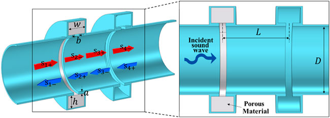
FIGURE 1. Schematic of a duct system side-coupled with double HRs. The double annular HRs are installed in a duct with sound wave incident from one side. The upstream resonator close to the sound incident side is stuffed with porous material.
In this model, the fundamental resonance mode
Here,
In addition, because the distance between the two resonators is not negligible, a phase difference exists between the outgoing (incoming) waves of the absorber and the incoming (outgoing) waves of the reflector. According to the transfer matrix method utilized in common acoustic waveguides, the relation can be described as (Cai and Mak, 2018):
where
From Eqs 1, 2, according to TCMT (Manolatou et al., 1999), we can derive
Substituting Eq. 9 into Eq. 4:
Similarly, substituting Eq. 10 into Eqs 5, 6 yields
For simplicity, we defined
Substituting Eqs 7, 8, 14, 15 into Eq. 11, and with some derivation, we can obtain the transmission coefficient
With similar derivation steps, the reflection coefficient
The absorption can be obtained using
In a two-port system, the maximum absorption
A numerical simulation technique was utilized to assist in fulfilling the critical coupling conditions. The eigenfrequency study of COMSOL Multiphysics software provides eigenfrequencies of the HR structure in the form of a complex number:
In practice, the energy dissipation of HR structures includes the leakage rate (
When only the pressure acoustic physics field is applied,
Through simulation, it was found that the insertion of a porous material in the HR cavity can directly convert most of the HR into the absorption state. Thus, HRs targeting different frequencies can be converted to absorbers using porous materials and can be used as reflectors when cavities remain empty. Such convenience frees the design process from the trouble of tuning geometrical parameters to find an absorption mode while considering the operation frequencies.
Results and discussions
Numerical simulations and analytical modeling were conducted to examine the acoustic performance of the designed muffler structure. Because the geometrical dimension is closely related to the acoustic performance, three sets of HR geometrical parameters, which lead to a relatively high reflection capability, were selected. Each set targets a different sound-absorption frequency. A numerical simulation model was constructed using a 2D symmetric model in COMSOL Multiphysics.
In the model, a perfectly matched layer condition was defined at both ends of the tube, and the background pressure field was used to generate an incident plane wave on the absorber side of the tube. A thermoviscous field was applied to the necks of the HRs, and a poroacoustic field was employed in the cavity of the absorber to simulate the effect of the porous material. The mesh size was defined to ensure that there were at least six elements at the smallest wavelength. To simplify the design process, neck lengths a and width b were kept unchanged. The constant parameter setting helps maintain a relatively stable bandwidth when tuning the operation frequencies (Wu et al., 2018). In all three cases, the height of cavity h was 40 mm, and the length and width of the neck were defined as a = 3 mm and b = 5 mm, respectively. The other detailed parameters of the HRs and corresponding eigenfrequencies under various physical field settings in COMSOL Multiphysics are presented in Table 1. The widths of the cavities were defined differently to adjust the resonant frequencies. As shown in the table, the eigenfrequencies satisfy
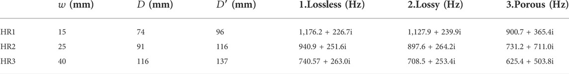
TABLE 1. Design parameters of the HRs targeting different frequencies.
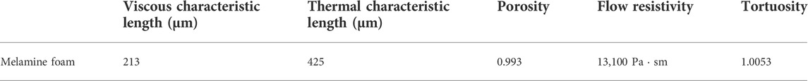
TABLE 2. Property parameters of the porous material melamine foam (Yang et al., 2015b).
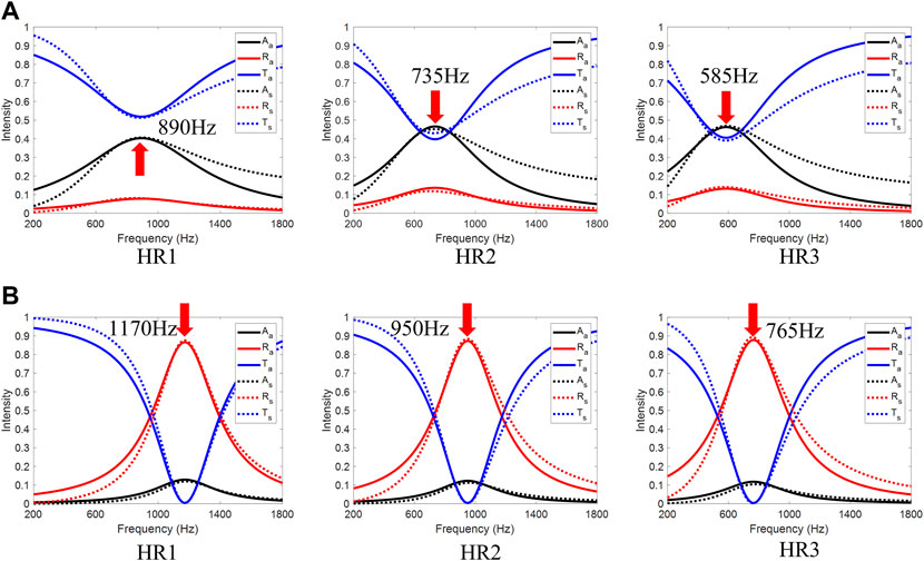
FIGURE 2. (A) Acoustic spectrum for HRi performing as absorbers, with the parameters:
Deviations were observed between the analytical and numerical results. This difference is attributed to the assumption that only the dominant resonant mode is considered in the analytical model, but higher-order resonance is also included in the simulation. In addition, the coupling of the two resonant modes was assumed to be weak and thus neglected in the analytical model.
The acoustic performance of the absorber and reflector combination was then explored experimentally for comparison with the simulation and numerical results. Prototypes were fabricated by additive manufacturing. Each prototype was designed to consist of three parts, by which the annular porous material could be conveniently inserted into the cavity. A photograph of the HR1 prototype is shown in Figure 3A. The parts were connected using screw bolts and nuts, and melamine foam was chosen as the porous material. Extra testing was conducted to ensure that the melamine foam samples had similar properties, as described in Table 2. The experimental setup is illustrated in Figure 3B. The prototype was tested by using a circular impedance tube (Fantwave F-Tube C). A standard four-microphone method was implemented to obtain the transmission, reflection, and absorption coefficients. The diameter of the tube was 100 mm, and the cut-off frequency was approximately 1800 Hz.
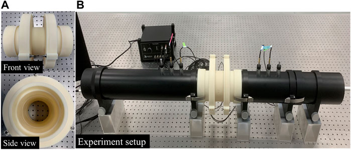
FIGURE 3. (A) Front and side view photograph of the muffler prototype manufactured by using the HR1 geometrical parameters. Porous material is cut as cyclic annular and put into the left HR cavity. (B) Experiment setting of the prototype.
For HR1, the measured results (denoted by subscript “e”) are presented in Figure 4A and are compared with the analytical and numerical results. The prototype revealed a maximum absorption of 95.6%, which was slightly larger than the 94.6% predicted in the simulation. The designed structure can achieve above 90% absorption at a 195 Hz width, from approximately 1,122 Hz–1,314 Hz. The experimental results were mostly consistent with the simulation, except that the maximum sound absorption frequency was approximately 80 Hz higher than that of the simulation. This deviation was mainly attributed to the geometrical error of the sample. The 3D printed epoxy material shrinks slightly after cooling and will therefore lead to unpredictable geometrical differences. The corresponding parameters in the analytical model are defined as:
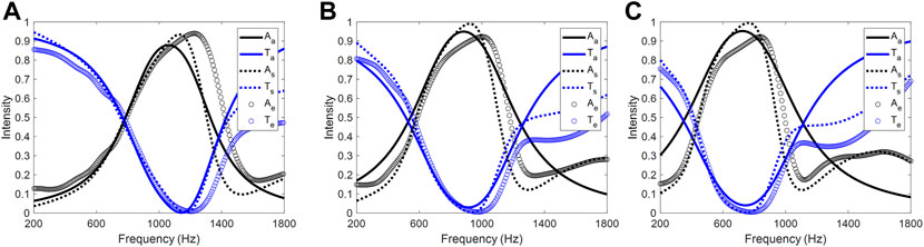
FIGURE 4. Acoustic spectrum of the muffler form by (A) HR1; (B) HR2; (C) HR3. The analytical (solid line), numerical simulation (dashed line) and experiments (dots) results are presented for comparison. The absorption and transmission coefficient are shown by black and blue curves respectively.
In addition, the analytically predicted absorption is relatively lower than the measured absorption because of the air damping effect. The coupling of both resonators changes the resonance properties, and thus the parameters of each resonator are different from those first investigated in the uncoupled model.
Simulation and experimental results of HR2 and HR3 are shown in Figures 4B,C, respectively. For HR2, the numerical calculated and measured results reveal that above 90% absorption can be achieved in the frequency range of 790–1,010 Hz and 920–1,082 Hz, respectively. Meanwhile, the absorption frequency ranges of HR3 in simulation and experiment are 605–825 Hz and 774–912 Hz, respectively. The measured data are approximately 100 Hz higher than the simulation results, yet the tendency and shape of the curves are the most consistent. These results indicate that the designed muffler structure can provide near-perfect absorption in the desired frequency range. The sound pressure level (SPL) of a duct installed with the proposed muffler is numerically investigated. For HR1—HR3, the SPL maps when incident waves are in the corresponding resonant frequencies are shown in Figure 5. According to the figure, one can find that the pressure is accumulated within the HR cavity. The SPL in the lower part of the duct is relatively low, indicating that the sound pressure is mostly attenuated. Table 3 lists the detailed analytical parameters and corresponding resonant frequencies for the three HR cases.
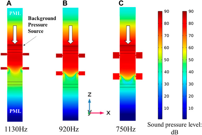
FIGURE 5. SPL map of ventilation duct when incident wave is in the resonant frequency of: (A) HR1; (B) HR2 and (C) HR3.
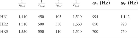
TABLE 3. Analytical parameter of the combined HR pairs.
Videos that reveal the sound absorption capability of HR1 in operation frequencies and ventilation status before and after the installation of the mufflers are recorded and provided in the Supplementary Material. The ventilation performance testing system comprised a pipeline blower, polyvinyl chloride (PVC) tubes, and designed annular HRs. The blower was installed on one port of the pipe system, and an air meter/sound level meter was used to test the transmitted flow speed/sound level on the other port. When the muffler was dismounted, it was replaced by a PVC tube with the same effective length to maintain the total duct length.
In the ventilation duct, the grazing flow can change the flow resistance of the perforated surface and the acoustic performance of the HR structures. However, the flow resistance is proportional to the flow’s Mach number (Wang et al., 2021), and a short neck length weakens the impact of grazing flow (Wu et al., 2019). The Mach number of the flow speed (about 7.1 m/s) in the ventilation test was approximately 0.02, and the neck length was small. Therefore, the effect of the grazing flow was neglected in this study. We then considered a structure with lossy resonators on both sides of the reflector unit. The configuration and a photograph of the prototype are shown in Figure 6A. Such a structural design allows the muffler to conduct sound absorption for waves incident from both sides of the tube and thus brings better feasibility in actual applications. In addition, the use of an extra absorber leads to an increase in absorption bandwidth. The test results are presented in Figure 6B. The experimental results are consistent with the simulation, except that the absorption bandwidth is broader than predicted. The roughness of the 3D printed sample is not carefully controlled during the manufacturing process and will therefore cause unexpected friction and broaden the bandwidth.
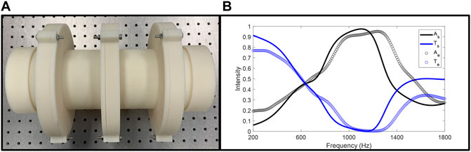
FIGURE 6. (A) Photograph of the muffler prototype with 3 HR units. The absorbers are allocated on both sides of the reflector HR. (B) Simulation and experiment results of the 3 HR units muffler.
The measured results indicate that the prototype can achieve sound absorption above 90% in the frequency range of 948–1,338 Hz (in simulation: 935–1,200 Hz). The measured bandwidth was 390 Hz, which is approximately 100% larger than that of the muffler with only one absorber.
Conclusion
We proposed a muffler design consisting of two coupled HR for sound absorption in a two-port ventilation system. The cross-section of the circular tube was not transformed after the installation of the designed muffler to avoid hindering ventilation. An analytical model based on TCMT was developed and verified. A convenient numerical method is introduced to assist in the design of the muffler.
An experimental study was conducted, and the results were verified using analytical and numerical results. The measured results show that the proposed muffler can achieve near-perfect sound absorption in a duct system while maintaining itself on a subwavelength scale. The symmetry allocation of the absorber resonator was also investigated to achieve an absorbing sound incident from both sides of the ventilation tube. The use of an extra absorber has been experimentally proven to result in a broader sound absorption bandwidth.
We believe that such a design mechanism and muffler structure provide a promising solution for sound absorption and noise reduction applications under ventilation conditions. The absorption operation frequency can be effectively tuned by adjusting the geometrical parameters of the HR structure and is thus suitable for different application scenarios.
Data availability statement
The raw data supporting the conclusions of this article will be made available by the authors, without undue reservation.
Author contributions
CG, CH, BH, and WW initiated the project; CG conducted the analytical derivation; JM and ZD helped with the analytical model equations; CH and XZ helped with data analysis and software support; CG carried out the numerical simulation and experimental work; WW provided funding support; CG drafted the initial manuscript and all authors equally contributed to the revision.
Funding
This research is supported by the Department of Science and Technology of Guangdong Province GDST20SC03 and the Project of Hetao Shenzhen-Hong Kong Science and Technology Innovation Cooperation Zone (HZQB-KCZYB-2020083).
Conflict of interest
Author CH is employed by Shenzhen Fantwave Tech. Co., Ltd.
The remaining authors declare that the research was conducted in the absence of any commercial or financial relationships that could be construed as a potential conflict of interest.
Publisher’s note
All claims expressed in this article are solely those of the authors and do not necessarily represent those of their affiliated organizations, or those of the publisher, the editors, and the reviewers. Any product that may be evaluated in this article, or claim that may be made by its manufacturer, is not guaranteed, or endorsed by the publisher.
Supplementary material
The Supplementary Material for this article can be found online at: https://www.frontiersin.org/articles/10.3389/fmats.2022.991959/full#supplementary-material
References
Cai, C., and Mak, C. M. (2018). Acoustic performance of different Helmholtz resonator array configurations. Appl. Acoust. 130, 204–209. doi:10.1016/j.apacoust.2017.09.026
Chen, S., Fan, Y., Yang, F., Jin, Y., Fu, Q., Zheng, J., et al. (2019). Engineering coiling-up space metasurfaces for broadband low-frequency acoustic absorption. Phys. Status Solidi RRL. 13, 1900426. doi:10.1002/pssr.201900426
Cummer, S. A., Christensen, J., and Alù, A. J. N. R. M. (2016). Controlling sound with acoustic metamaterials. Nat. Rev. Mat. 1, 16001–16013. doi:10.1038/natrevmats.2016.1
Dong, R., Sun, M., Mo, F., Mao, D., Wang, X., and Li, Y. (2021). Recent advances in acoustic ventilation barriers. J. Phys. D. Appl. Phys. 54, 403002. doi:10.1088/1361-6463/ac1228
Fan, J., Zhang, L., Wei, S., Zhang, Z., Choi, S. K., Song, B., et al. (2021). A review of additive manufacturing of metamaterials and developing trends. Mater. Today 50, 303–328. doi:10.1016/j.mattod.2021.04.019
Gao, N., Wang, B., Lu, K., and Hou, H. (2021). Complex band structure and evanescent Bloch wave propagation of periodic nested acoustic black hole phononic structure. Appl. Acoust. 177, 107906. doi:10.1016/j.apacoust.2020.107906
Huang, S., Fang, X., Wang, X., Assouar, B., Cheng, Q., and Li, Y. (2018). Acoustic perfect absorbers via spiral metasurfaces with embedded apertures. Appl. Phys. Lett. 113, 233501. doi:10.1063/1.5063289
Huang, Y., Li, J., Chen, W., and Bao, R. (2019). Tunable bandgaps in soft phononic plates with spring-mass-like resonators. Int. J. Mech. Sci. 151, 300–313. doi:10.1016/j.ijmecsci.2018.11.029
Jimenez, N., Romero-Garcia, V., Pagneux, V., and Groby, J. P. (2017). Rainbow-trapping absorbers: Broadband, perfect and asymmetric sound absorption by subwavelength panels for transmission problems. Sci. Rep. 7, 13595. doi:10.1038/s41598-017-13706-4
Kim, S. R., Kim, Y. H., and Jang, J. H. (2006). A theoretical model to predict the low-frequency sound absorption of a Helmholtz resonator array. J. Acoust. Soc. Am. 119, 1933–1936. doi:10.1121/1.2177568
Kino, N. (2015). Further investigations of empirical improvements to the Johnson–Champoux–Allard model. Appl. Acoust. 96, 153–170. doi:10.1016/j.apacoust.2015.03.024
Kumar, S., and Lee, H. P. (2020). Labyrinthine acoustic metastructures enabling broadband sound absorption and ventilation. Appl. Phys. Lett. 116, 134103. doi:10.1063/5.0004520
Kushwaha, M. S., Halevi, P., Dobrzynski, L., and Djafari-Rouhani, B. (1993). Acoustic band structure of periodic elastic composites. Phys. Rev. Lett. 71, 2022–2025. doi:10.1103/PhysRevLett.71.2022
Lee, T., Nomura, T., Dede, E. M., and Iizuka, H. J. A. P. L. (2020). Asymmetric loss-induced perfect sound absorption in duct silencers. Appl. Phys. Lett. 116, 214101. doi:10.1063/5.0009631
Lee, T., Nomura, T., and Iizuka, H. (2019). Damped resonance for broadband acoustic absorption in one-port and two-port systems. Sci. Rep. 9, 13077. doi:10.1038/s41598-019-49222-w
Li, Y., and Assouar, B. M. (2016). Acoustic metasurface-based perfect absorber with deep subwavelength thickness. Appl. Phys. Lett. 108, 063502. doi:10.1063/1.4941338
Li, Y., Shen, C., Xie, Y., Li, J., Wang, W., Cummer, S. A., et al. (2017). Tunable asymmetric transmission via lossy acoustic metasurfaces. Phys. Rev. Lett. 119, 035501. doi:10.1103/physrevlett.119.035501
Liu, H., Wu, J. H., and Ma, F. (2021). Dynamic tunable acoustic metasurface with continuously perfect sound absorption. J. Phys. D. Appl. Phys. 54, 365105. doi:10.1088/1361-6463/ac0ab9
Liu, Z., Zhang, X., Mao, Y., Zhu, Y. Y., Yang, Z., Chan, C. T., et al. (2000). Locally resonant sonic materials. Science 289, 1734–1736. doi:10.1126/science.289.5485.1734
Long, H., Cheng, Y., and Liu, X. (2017). Asymmetric absorber with multiband and broadband for low-frequency sound. Appl. Phys. Lett. 111, 143502. doi:10.1063/1.4998516
Long, H., Liu, C., Shao, C., Cheng, Y., Tao, J., Qiu, X., et al. (2020). Tunable and broadband asymmetric sound absorptions with coupling of acoustic bright and dark modes. J. Sound Vib. 479, 115371. doi:10.1016/j.jsv.2020.115371
Ma, F., Wang, C., Du, Y., Zhu, Z., and Wu, J. H. (2022). Enhancing of broadband sound absorption through soft matter. Mat. Horiz. 2, 653–662. doi:10.1039/d1mh01685g
Ma, G., and Sheng, P. (2016). Acoustic metamaterials: From local resonances to broad horizons. Sci. Adv. 2, e1501595. doi:10.1126/sciadv.1501595
Ma, G., Yang, M., Xiao, S., Yang, Z., and Sheng, P. (2014). Acoustic metasurface with hybrid resonances. Nat. Mat. 13, 873–878. doi:10.1038/nmat3994
Ma, G., Yang, M., Yang, Z., and Sheng, P. (2013). Low-frequency narrow-band acoustic filter with large orifice. Appl. Phys. Lett. 103, 011903. doi:10.1063/1.4812974
Manolatou, C., Khan, M. J., Fan, S., Villeneuve, P. R., Haus, H. A., and Joannopoulos, J. (1999). Coupling of modes analysis of resonant channel add–drop filters. IEEE J. Quantum Electron. 35, 1322–1331. doi:10.1109/3.784592
Mei, J., Ma, G., Yang, M., Yang, Z., Wen, W., and Sheng, P. (2012). Dark acoustic metamaterials as super absorbers for low-frequency sound. Nat. Commun. 3, 756. doi:10.1038/ncomms1758
Meng, C., Zhang, X., Tang, S. T., Yang, M., and Yang, Z. (2017). Acoustic coherent Perfect absorbers as sensitive null detectors. Sci. Rep. 7, 43574. doi:10.1038/srep43574
Merkel, A., Theocharis, G., Richoux, O., Romero-García, V., and Pagneux, V. (2015). Control of acoustic absorption in one-dimensional scattering by resonant scatterers. Appl. Phys. Lett. 107, 244102. doi:10.1063/1.4938121
Pelat, A., Gautier, F., Conlon, S. C., and Semperlotti, F. (2020). The acoustic black hole: A review of theory and applications. J. Sound Vib. 476, 115316. doi:10.1016/j.jsv.2020.115316
Shao, H., He, H., Chen, Y., Tan, X., and Chen, G. (2020). A tunable metamaterial muffler with a membrane structure based on Helmholtz cavities. Appl. Acoust. 157, 107022. doi:10.1016/j.apacoust.2019.107022
Sigalas, M., and Economou, E. N. (1993). Band structure of elastic waves in two dimensional systems. Solid State Commun. 86, 141–143. doi:10.1016/0038-1098(93)90888-t
Wang, J., Rubini, P., and Qin, Q. (2021). A porous media model for the numerical simulation of acoustic attenuation by perforated liners in the presence of grazing flows. Appl. Sci. 11, 4677. doi:10.3390/app11104677
Wei, P., Croënne, C., Tak Chu, S., and Li, J. (2014). Symmetrical and anti-symmetrical coherent perfect absorption for acoustic waves. Appl. Phys. Lett. 104, 121902. doi:10.1063/1.4869462
Wu, G., Lu, Z., Xu, X., Pan, W., Wu, W., Li, J., et al. (2019). Numerical investigation of aeroacoustics damping performance of a Helmholtz resonator: Effects of geometry, grazing and bias flow. Aerosp. Sci. Technol. 86, 191–203. doi:10.1016/j.ast.2019.01.007
Wu, X., Au-Yeung, K. Y., Li, X., Roberts, R. C., Tian, J., Hu, C., et al. (2018). High-efficiency ventilated metamaterial absorber at low frequency. Appl. Phys. Lett. 112, 103505. doi:10.1063/1.5025114
Xiang, X., Wu, X., Li, X., Wu, P., He, H., Mu, Q., et al. (2020). Ultra-open ventilated metamaterial absorbers for sound-silencing applications in environment with free air flows. Extreme Mech. Lett. 39, 100786. doi:10.1016/j.eml.2020.100786
Yang, M., Li, Y., Meng, C., Fu, C., Mei, J., Yang, Z., et al. (2015). Sound absorption by subwavelength membrane structures: A geometric perspective. Comptes Rendus Mécanique 343, 635–644. doi:10.1016/j.crme.2015.06.008
Yang, M., Ma, G., Yang, Z., and Sheng, P. (2016). Subwavelength perfect acoustic absorption in membrane-type metamaterials: a geometric perspective. EPJ Appl. Metamaterials 2, 10. doi:10.1051/epjam/2015017
Yang, M., Meng, C., Fu, C., Li, Y., Yang, Z., and Sheng, P. (2015). Subwavelength total acoustic absorption with degenerate resonators. Appl. Phys. Lett. 107, 104104. doi:10.1063/1.4930944
Keywords: helmholtz resonator, duct muffler, ventilation duct, sound absorption, porous material
Citation: Gao C, Hu C, Mei J, Hou B, Zhang X, Du Z and Wen W (2022) Barrier-free duct muffler for low-frequency sound absorption. Front. Mater. 9:991959. doi: 10.3389/fmats.2022.991959
Received: 12 July 2022; Accepted: 10 August 2022;
Published: 07 September 2022.
Edited by:
Weihua Li, University of Wollongong, AustraliaReviewed by:
Weiwei Kan, Nanjing University of Science and Technology, ChinaGuolin Yun, University of Cambridge, United Kingdom
Copyright © 2022 Gao, Hu, Mei, Hou, Zhang, Du and Wen. This is an open-access article distributed under the terms of the Creative Commons Attribution License (CC BY). The use, distribution or reproduction in other forums is permitted, provided the original author(s) and the copyright owner(s) are credited and that the original publication in this journal is cited, in accordance with accepted academic practice. No use, distribution or reproduction is permitted which does not comply with these terms.
*Correspondence: Chuandeng Hu, Ym9zb25AZmFudHdhdmUuY29t; Jun Mei, cGhqdW5tZWlAc2N1dC5lZHUuY24=; Weijia Wen, cGh3ZW5AdXN0Lmhr