 P. D. Mulye
 L. Morançay2
 C. Binetruy
 S. Comas-Cardona
- 1Nantes Université, École Centrale Nantes, CNRS, GeM, Nantes, France
- 2Altair Engineering France, Valbonne, France
- 3Pôle Ingénierie Polymères & Composite, CETIM, Technocampus Composites, Bouguenais, France
The main idea behind “Quilted Stratum Process” (QSP®) is to create a flat blank made of unidirectional/woven thermoplastic prepreg patches instead of using uniformly shaped prepreg stack as is the case with standard thermostamping process. Thus, using QSP®; one can manufacture components with complex geometries by using nearly rectangular patches while still maintaining a short cycle time similar to the standard thermostamping process. The use of near-rectangular patches results in a significant material saving which is a necessity for a sustainable product development. During standard thermostamping and/or QSP®; the consolidation phase plays a key role in the strength and quality of the final product. This becomes even more important in the case of unidirectional thermoplastic prepregs where mechanisms such as transverse squeeze flow can impact not only the in-plane dimensions of the prepreg but also the fibre orientations within the prepreg. This work presents a unified modeling approach that combines a novel pinching shell element, a new elasto-plastic constitutive model for pinching shell in order to provide a unified solution to simulate both forming and consolidation-flow using a shell-based approach. This unique unified approach of simulating forming and consolidation provides a set of additional outputs such as the through-thickness stress, final deformed shape of the plies including the squeeze flow effect and the changes in the orientation of fibres within the plies during and after the process. This work finally demonstrates how this information can help the manufacturers to design better tooling based on the outcomes of the numerical process simulation in order to achieve a desired product quality. Additionally, one can also steer the final fibre orientation which results from the initial position of the patch, its forming and squeeze flow.
1 Introduction
The classical thermostamping process for manufacturing composite parts has been around for many years. A modified version of this process called “Quilted Stratum Process” (QSP®) (Guillon et al., 2016) has been developed in 2012 by CETIM, Centrale Nantes and other partners. The motivation behind this advanced manufacturing technology is to strategically optimize a component’s performance while reducing material wastage without compromising the production process efficiency.
QSP® shares several features with the standard composite thermostamping process. However, the main idea behind this process is to use unidirectional (UD) or woven thermoplastic prepreg patches instead of using uniformly shaped prepreg stack as is the case with standard thermostamping process. By using smaller and near-rectangular patches; the flat prepreg geometry can be optimally subdivided so as to fit maximum number of patches within a given size of the prepreg sheet at the prepreg cutting phase (Figure 1) which reduces the material wastage. This reduction in material wastage not only decreases the production cost but also reduces the environmental impact, thereby creating a more sustainable solution compared to the classical thermostamping process. In addition, by choosing the specific prepreg patches for specific locations, one provides an additional degree of freedom in the design of the part using QSP® (Irisarri et al., 2019). It is true that some material overlap might be required in case of QSP® (Figure 1). However, in case of classical thermostamping; the material corresponding to the areas that inside the circular shapes in (Figure 1) is wasted. This wastage, in general much bigger than the extra material needed for the overlap can be avoided by using QSP®. Further, by using specific patches at specific locations on the part, one can create local strengthening of the part [refer to Figure 6 from Guillon et al. (2016) to see an example of a local strengthening of a component]. On the other hand, in case of a classical thermostamping process, this kind of local strengthening may not be easy to obtain and it would have to be a global strengthening (using multiple plies everywhere instead of just specific locations) which would require much more material.
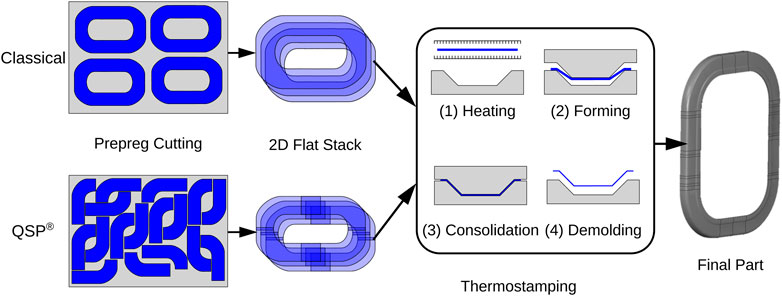
FIGURE 1. A schematic representation of a full workflow of a thermostamping process for a classical process as well as QSP® for a demonstrator of an aircraft window frame from a SHERLOC QSP® project (Thomas J and Charlotte, 2019) (a part of CLEAN SKY 2 initiative).
In order to embrace the idea of “one-shot-manufacturing”; it is important to consider all the major features of a given manufacturing process and their impact on the final product. Thus numerical simulation of a process and its inclusion into the product design pipeline is very important. Driven by the anisotropic nature of fabric coupled with its interaction with the polymer in case of prepregs, numerical simulation of a standard composite forming process itself poses several challenges. However for QSP®, there are some additional challenges in the physical process and its numerical modeling because of the usage of prepreg patches: the inability to use a blank holder, the possible long distance sliding of prepreg patches during forming (Schell et al., 2016) and the transverse squeeze flow occurring during consolidation especially for UD prepregs.
The overview of the modeling of a classical composite forming process can be found in (Lim and Ramakrishna, 2002; Dörr et al., 2017a) the latter addresses the available industrial solutions for simulation of UDs. For an even more recent review about the advances in composite forming, one can refer to (Boisse et al., 2022). In 2018, it has been showed in the review article (Bussetta and Correia, 2018) that the major focus of the research in composite forming simulation has been on the forming phase of the process and more specifically, on the modeling of in-plane shear and tension to predict changes in fibre orientations and prediction of wrinkles.
However, during standard thermostamping and/or QSP®; the forming stage is almost always followed by a consolidation stage which is relatively less explored. Consolidation stage helps in removal of porosities, healing ply-ply interfaces, improving the surface quality and controlling the thermo-mechanical transformations of the material at the onset of the cooling phase. Thus, the consolidation phase plays a key role in the strength and quality of the final product.
During the consolidation process of thermoplastic prepregs, there exists a through-thickness normal (transverse) stress also referred to as “Pinching Stress” (Soulat et al., 2006) which in fact is the main driving mechanism of the consolidation phase. The modeling of the consolidation phase becomes even more important in the case of unidirectional thermoplastic prepregs where mechanisms such as transverse squeeze flow can impact not only the in-plane dimensions of the prepreg but also the fibre orientations within the prepreg (Sorba et al., 2017). The mechanism of the transverse squeeze flow is schematically shown in Figure 2. In this mechanism, due to the consolidation pressure, the thickness of the composite layer reduces, creating a resin movement within the ply which in turn convects the fibres with it (provided there is a room for the material to flow in-plane) and modifies the fibre orientations. It is to be noted that the resin-rich layer exists at the ply-ply interface in almost all types of layups as discussed in (Sorba et al., 2017). This resin-rich layer facilitates the movement of the fibres in the adjacent layers even in the case of multidirectional layups which has been demonstrated in their work on a stack configuration of[0°/90°]6.
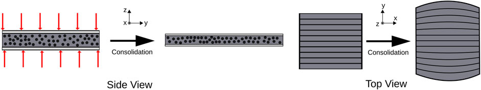
FIGURE 2. A schematic representation of a transverse squeeze flow mechanism for a single unidirectional ply (without any lateral constraints) during the consolidation phase of the thermostamping process.
The experimental evidence of the transverse squeeze flow and its influence on the final component is demonstrated in Figure 3. Figure 3A shows the initial and final deformed shape of a UD stack of [0°]5 after undergoing a 25% consolidation. Due to the inextensibility of the fibres, the major deformations occur along the direction orthogonal to the fibres. This transverse stretching can be very high (in this case the final width was 1.5 times the original width). Figure 3B shows an industrial scale component manufactured by CETIM which has a UD patch at the top in its stacking configuration. It can be seen that the initial width of 78 mm can increase by as much as 30% at several locations due to the transverse squeeze flow. In summary, the mechanisms such as in-plane shear and tension are relatively well established in the literature both in terms of simulation as well as their characterization. On the other hand, the mechanisms such as the squeeze flow and simulation of consolidation are not yet standardized, even though their influence on the final deformed shape is obvious.
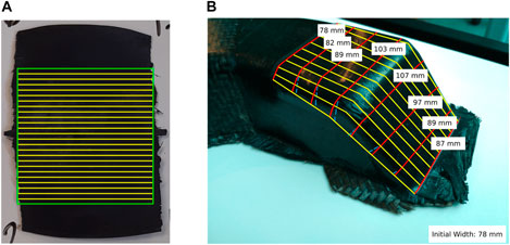
FIGURE 3. Experimental evidence of the transverse squeeze flow mechanism. (A) Final deformed shape of a flat [0°]5 stack after consolidation (the initial shape is shown in green color and the initial fibre orientations are shown in yellow color); (B) Final deformed shape of a unidirectional patch of an industrial component manufactured using QSP® by CETIM (the fibre orientations are shown in yellow color and the final width measurements at various locations are shown).
In order to incorporate both forming and consolidation phases into the process simulation, a natural strategy could be to use a two-step approach to simulate forming and consolidation phases serially one after the other. This is motivated by the fact that the primary mechanisms occurring in forming and consolidation phases are quite different. However, this strategy poses several practical challenges from a numerical simulation point of view.
Without the pinching shell element, the two-step approach would be: 1) perform the forming simulation using classical shell elements 2) export the deformed mesh and other data after the forming phase 3) add a hexahedral elements layer (to model through thickness compressive behavior during consolidation) in between the plies modeled with classical shell elements 4) perform consolidation phase simulation.
This two-step approach was tested on an industrial model and the practical challenges that were observed were as follows [discussed in more detail in (Mulye, 2021)]:
• At the end of the forming stage, the shell components (plies) are already in a 3D deformed configuration and often there could be regions with a very small gap between the plies. This results in a very small thickness of hexahedral elements that are added in such regions. This in turn results in a very small time-step for consolidation.
• Because the nature of the Type-25 contact in Altair Radioss™(constant penalty stiffness) that is added between the plies (during forming); often the midsurfaces of the plies can themselves interpenetrate making it impossible to add a hexahedral layer in such locations.
• A user intervention is needed to make a decision about the resolution of the above two points. This makes it challenging to make the whole process automated which can be a big hurdle from an industrial point of view.
Besides, it has been shown in (Soulat et al., 2006) that porosities in some regions can get removed during forming phase itself indicating a possibility of a local consolidation even during the forming phase. Thus, creating a global split of the forming and consolidation phases may not be possible. This has motivated us to develop a unified modeling strategy that can be used for both forming and consolidation phases without the need to explicitly separate them.
In the literature, the forming phase is predominantly modeled using shell elements whereas there have been three main directions for modeling consolidation process from the point of view of the finite element used in the numerical simulation: 1) solid (hexahedral) element based approach 2) solid-shell element based approach 3) shell element based approach.
The solid elements can readily capture a 3D stress state without requiring any changes in the existing element formulations or modifications in the constitutive models. The numerical modeling of consolidation process conducted in (Belnoue et al., 2016; 2018) used C3D8 solid elements of ABAQUS/Standard to model each individual ply with a specific user material model. A solid element with 27 nodes with a mixed formulation for velocity, pressure and fibre tension was used in (Sorba et al., 2017) to model transverse squeeze flow by modeling the UD prepregs as a transversely isotropic viscous fluid (Rogers, 1989). Solid elements face challenge when they are thin (the thickness of a prepreg is usually small compared to its in-plane dimensions) suffer from a small time-step in the case of an explicit solver and are too stiff/rigid in bending mode due to the transverse shear locking phenomenon.
A solid-shell element has a 3D stress state and is able to overcome the limitation of the transverse shear locking and therefore can also be used for bending modes. A novel prismatic solid-shell element with seven nodes (SB7γ19) was developed in (Xiong, 2017; Xiong et al., 2018; 2019) to model forming and consolidation in a unified manner, however effects such as transverse squeeze flow were not modeled as the focus was more on the woven prepregs instead of UD. A new hexahedral solid-shell element capable of pinching (SB9) was developed in (Dia et al., 2020) also to perform a unified simulation of forming and consolidation. Based on the work of (Schwarze and Reese, 2011), a new user element was implemented and extended in (Schäfer et al., 2020; Schäfer et al., 2021) with a major focus on the investigation of various locking mechanisms. Overall, the solid-shell elements show a good potential and when coupled with a selective mass scaling, they can be used to simulate forming and consolidation on an industrial scale. However, a demonstration on a full-scale industrial model with many plies and prepreg patches (QSP®) is not available in the literature yet.
Even though the shell elements have shown tremendous potential for forming phase simulation which involves large deformations, large bending, large rotations; the classical 3-parameter (Kirchhoff-Love theory) or 5-parameter (Reissner-Mindlin theory) shells cannot be used for modeling consolidation as they are based on a plane stress assumption (i.e., σzz = 0). So they cannot have a pinching stress. However, a 6-parameter shell proposed in (Simo et al., 1990) has a possibility of stretching of the director vector with a linear displacement field along the thickness direction. Thus, it can have a σzz ≠ 0 and ϵzz ≠ 0; however it suffers from a Poisson thickness locking which can be resolved either by decoupling pinching stress and bending strains (Soulat et al., 2006) or by using a quadratic interpolation of displacement along the thickness (Parisch, 1991; Sansour and Bufler, 1992). Further, a 7-parameter shell (Büchter and Ramm, 1992; Büchter et al., 1994) which is by far the most comprehensive shell formulation can also have a pinching stress. further discussion about this type of shell can be found in (Bischoff and Ramm, 1997; 2000; Brank et al., 2002).
In conclusion, developing a purely shell element based approach for modeling consolidation can be impactful as the current typical simulation workflow involves shell elements for modeling forming. Thus, having a shell element that can be used for both forming and consolidation phases in a unified manner can be beneficial as it would require no or very little change to the current workflow in the industries. To the best of our knowledge, there is no unique numerical solution that is able to address both forming and consolidation phases (with or without long distance sliding of prepreg patches) together in a unified manner that is solely based on the shell approach.
This work presents such a shell-based unified modeling approach that combines a novel pinching shell element, elasto-plastic constitutive model for pinching shell and the interply adhesion model (Mulye et al., 2020) in order to provide a unified solution to model both forming and consolidation-flow. This unique unified approach of simulating forming and consolidation provides a set of additional outputs such as the through-thickness stress, the final deformed shape of the plies including the squeeze flow effect and the changes in the orientation of fibres within the plies during and after the process. This information is useful as it helps in identifying the regions which will have a good consolidation quality versus the regions with poor consolidation quality. Also, assuming good consolidation is achieved, by observing the changes in the fibre orientations caused by the squeeze flow, one can determine whether the component meets or not the required quality in terms of strength. Using this information, and by performing several design and process simulation iterations; one is able to obtain a better final design of the mold and/or stack itself that incorporates all the necessary ingredients of the full manufacturing process.
2 Objectives and content of the study
The main objectives of this study are fourfold:
• Develop a new shell element (QBATP) by extending the hourglass-free full-integration 4-node QBAT shell element of Altair Radioss™ so as to include a transverse normal (pinching) stress
• Propose a novel elasto-plastic constitutive model for the QBATP shell to model the behavior of the nearly incompressible melt polymer during the consolidation phase and propose a practical method for its characterization
• Create and validate a modeling strategy using the above two points in order to provide a unified approach of process modeling of forming and consolidation
• Demonstrate the use of this strategy to improve the mold design for thermoplastic composites
3 A full-integration pinching shell (QBATP)
As discussed above, the three-dimensional stress state cannot be modeled with the classical 5-parameter Mindlin shells which are built with a plane-stress assumption (σzz = 0). To overcome this, a new 4-noded 6-parameter shell element (referred to as QBATP which stands for “Quadrilateral BAToz Pinching shell element”) has been developed by extending the existing hourglass-free full-integration 5 parameter shell element in Altair Radioss™ known as QBAT (Altair Engineering, 2018). The QBAT element is based in the Q4γ24 element discussed in Batoz and Dhatt (1992) which in turn is based on the MITC4 element discussed in Bathe et al. (1975), Dvorkin and Bathe (1984). The functionality of the pinching stress has been added by introducing additional nodal degrees of freedom to the existing QBAT formulation, discussed in this section.
In this work, a 6-parameter shell element (linear displacement interpolation through thickness) was chosen and the Poisson thickness locking was avoided by decoupling the normal pinching stress and the bending (discussed further in Section 3.3). The 7-parameter shell (quadratic displacement interpolation through thickness) would have readily solved the Poisson thickness locking problem without any modifications to the constitutive model. However, the choice of 6-parameter shell over a 7-parameter shell in this work was mainly driven by the associated computational cost which would be lower in case of a 6-parameter shell because of lesser degrees of freedom per node compared to a 7-parameter shell.
3.1 Concept of pinching and shell element description
A typical geometry of a general shell element can be represented as shown in Figure 4A by a three-dimensional mid-surface
and ξ, η and ζ are the parametric coordinates and h is the thickness of the shell. In general, the nodal fiber direction ζ may not correspond to the mid-surface normal
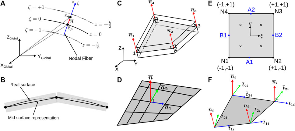
FIGURE 4. QBATP shell element: (A) Formulation and representation of the nodal fiber; (B) Representation of QBATP shell element; (C) Representation of the geometry of the element; (D) Covariant basis for the shell; (E) Reference element in isoparametric space; (F) Nodal orthogonal coordinate systems.
Using the first order approximation of Taylor series for
The Term 1 in Eq. 3 corresponds to the displacement DoFs of the mid-surface of the shell. The Term 2 corresponds to the rotation DoFs of the mid-surface. The Term 3 corresponds to the change in thickness. This phenomenon is neglected in the case of classic shell theories; as the fiber (not to be confused with the fibres that provide reinforcements for the composites) is assumed to be inextensible (Belytschko et al., 2013). As a result, only the first two terms are considered for the classical shells. However, the Term 3 is not neglected for the six or seven parameter shells. This term is the basis of creating an additional nodal degree of freedom locally referred to as the “Pinching degree of freedom.” Taking into account the Term 3 in the shell formulation, it is possible to have a non-zero transverse normal stress σzz.
The geometry of QBATP shell is shown in Figure 4C which consists of four nodes on the mid-surface of the shell. The corresponding reference element in the isoparametric space along with the local node numbering convention is shown in Figure 4E. Classical bilinear shape functions and their derivatives are used to interpolate a nodal degree of freedom. Within the element, each node (i) has six local degrees of freedom; three for standard mid-surface displacements (U1i, U2i, U3i), two for rotations (θ1i, θ2i) and additionally one for the pinching displacement
which are defined with respect to the orthonormal coordinate system (
The pinching DoFs are defined with respect to the mid-surface. The pinching displacement Up corresponds to the displacement of the artificial nodes located at the top and bottom surface of the shell. This being a relative degree of freedom, a sign convention needs to be defined. The increase of thickness is considered positive, i.e., Up > 0 whereas a reduction of the thickness is considered to be negative, i.e., Up < 0.
3.2 Calculation of strain-rates and strain
Strain rates are calculated based on the rate of deformation tensor. The calculation of the strain rates is split into four strain interpolation matrices 1) Membrane [Bm] 2) Curvatures [Bb] 3) Pinching [Bp] and 4) Transverse shear [Bts]. The details for the individual strain rate matrices can be found in the Supplementary Material (Section 2) of this article.
The membrane strain-rate is calculated as follows:
Where the [Bm] matrix is given by:
The rates of curvature are calculated as follows:
Where the [Bb] matrix is given by:
The pinching strain-rate is calculated as follows:
Where the [Bp] matrix is given by:
While considering the transverse shear behavior, it is important to consider the phenomenon of “Transverse Shear Locking.” This occurs mainly because of the inability of the C0 shell finite elements to reproduce a pure bending behavior. The coupling between the normal and shear strains for linear elements results in a parasitic transverse shear strains in case of pure bending. This therefore, leads to numerical stiffening in bending creating a poor convergence. There are several solutions discussed in the literature to avoid this type of locking. Methods such as reduced integration of the transverse shear as discussed in (Oñate, 2013), usage of C1 elements as discussed in (Belytschko et al., 2013), the “Enhanced Assumed Strain” (EAS) method proposed in (Simo and Rifai, 1990) and the “Assumed Natural Strain” (ANS) method first proposed in (Hughes and Tezduyar, 1981) can be used. This idea of “Assumed Natural Strain” (ANS) method has been discussed in (Dvorkin and Bathe, 1984) and further used for Q4γ24 element in (Batoz and Dhatt, 1992). In this work, the same approach has been used for the QBATP elements. The method interpolates the transverse shear strain from the values of the covariant components of the transverse shear strains at four edge mid-points (A1, A2, B1, B2) as follows Figure 4E,
With this, the transverse shear strain-rate is calculated as follows:
Where the [C0] is the local basis at z = 0 (Refer to Section 1 in Supplementary Material) and the [Bts] matrix is given by:
3.3 Elastic constitutive model
The incremental form of the elastic constitutive model discussed in Soulat et al. (2006) was used in this work as a first step. It is to be noted here that the final modeling strategy is as follows: each ply in a multi-layer composite stack is modeled individually. Each of these plies consists of two shell element components with shared coincident nodes (discussed later in more detail in Section 4 of this work). In brief, one shell component would represent fibres using an anisotropic elastic material model, whereas the other shell components would represent the melt polymer using an elasto-plastic constitutive model developed and discussed later in Section 4. Developing an elastic constitutive model serves as the first step in order to validate the shell element itself before continuing with the next developments.
The membrane and bending contributions to the stress which use the corotational framework are as follows:
where the Δϵij correspond to the change of membrane strains whereas the Δχij correspond to the change of curvatures.
Compared to the classic QBAT shell, the modifications are as follows:
• The membrane stiffness matrix for the QBATP element does not use the plane stress assumption. Therefore, it is similar to the full three-dimensional stiffness matrix for elasticity.
• QBATP element has an additional stress compared to QBAT shell, i.e., the transverse normal stress σzz.
•σzz has been decoupled from the bending DoFs in order to avoid pinching locking (or Poisson thickness locking) as discussed in more detail in Soulat et al. (2006). This assumption of decoupling can and will result in errors such as the underestimation of the total strain energy. However, we believe that in composite applications; it is rare to find a material point that is undergoing forming and consolidation at the same time (which is where one will expect the most errors because of this assumptions). Each material point in a ply can switch from forming to consolidation at a different time during the entire process, but the material point is either undergoing forming (i.e., bending) or consolidation (i.e., transverse normal compression) at a given instant.
In this work, the through-thickness integrations are calculated explicitly without at each gauss points performing numerical integration. This approach is referred to as a “global approach” as it does not use any integration points in the thickness direction.
3.4 Stress internal force relationship
The internal force vector (Fint) for the element is then calculated as,
This three-dimensional integration is then split into a through-thickness integration and subsequently a surface integration over the element’s mid-surface. The stress resultants are calculated as follows:
And the stress couples are calculated as follows:
This results into a Fint vector for the element as follows,
These are then assembled after performing necessary coordinate transformations into separate vectors for global Forces
3.5 External force and pinching pressure
In order to apply an external load for pinching the element, a surface type of loading for pinching has been developed. It is referred to as ‘Pinching pressure’ in this work. This involves application of an equal and opposite surface pressure load (P) on the top and bottom sides of the shell. The external pinching force at each node (i) of the element is calculated as,
Where A is the area of the element and
It is to be noted here that the development of the pinching pressure type of loading is purely done to test the shell element under external pinching load. It serves as a checkpoint before beginning the development of the interaction between the contact forces and the pinching degrees of freedom. In thermostamping applications, one cannot actually apply a pinching load directly. Pinching/consolidation will occur through contact forces, and it will get transmitted from one ply to the other through contact forces. This physics of contacts and their interaction with pinching degrees of freedom has been implemented in Altair Radioss™ details of which can be found in Mulye (2021).
3.6 Dynamic system of equations
The assembly of internal and external forces, moments and pinching forces results in the following global dynamic system of equations (Eq. 24). It consists of three sets of equations each corresponding to displacements, rotations and pinching displacements respectively.
Where M and Mp are lumped mass matrices corresponding to the displacements and pinching displacements respectively. I is the diagonal moment of inertia. An explicit central difference scheme that falls under the broad category of Newmark family schemes with α = 1/2 and β = 0 is used in Altair Radioss™ (Altair Engineering, 2018) to solve this system of equations in order to obtain the velocities and displacements at each time-step.
Further, selective mass scaling has been added for this element to increase its critical time-step. In the case of QBATP element; an approach inspired from the technique of the acceleration filtering for solid elements (Olovsson et al., 2004) was used. This approach is similar to the selective mass scaling for solid-shell elements discussed in Cocchetti et al. (2013). This allowed one to selectively increase the mass corresponding only to the pinching DoFs (Mp) without changing the mass for the classical DoFs (M). A detailed discussion about selective mass scaling for QBATP shell element can be found in Section 3.4 of Mulye (2021). With the implementation of the selective mass scaling, the time-step of the QBATP shell element does not depend on its thickness. This comes at a price that the dynamic effects along the thickness can no longer be modeled. However forming and consolidation can be considered to be quasi-steady processes for which it is a fair assumption to neglect the dynamic effects along the thickness direction.
Additionally, in order to use QBATP shell element for the simulation of forming and consolidation; it is necessary to add the capability of pinching within the contact interface. This capability has been added for the Type-25 contact interface in Altair RadiossTMand has been validated with a test case discussed in Mulye (2021).
It is important to mention here all the code developed in this work can be accessed within the GitHub repository of OpenRadioss (Altair Engineering, 2022).
3.7 Validation
Before performing any full-scale unified simulation using the QBATP shells, it is necessary to validate the shell element itself which is done using various numerical tests. Even though only three of the numerical validations tests are discussed in this section, other numerical tests can be found in Mulye (2021) and the corresponding simulation input files can be found in the Supplementary Material (Section 5) of this article.
3.7.1 Uniform crushing under pressure test
The objective of this numerical test is to compare the QBATP element (with selective mass scaling) with the BRICK8 element of Altair Radioss™ under a uniform pinching pressure and also compare the results with the values reported in Soulat et al. (2006). The geometry consists of flat plate of size 50 mm × 50 mm with an initial thickness of 4 mm which was meshed with an element size of 10 mm. The material properties of E = 120 GPa and
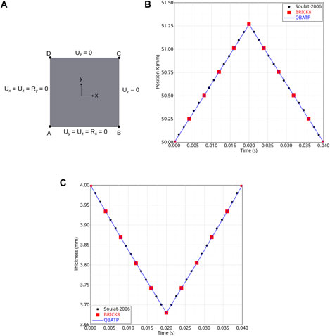
FIGURE 5. QBATP validation test: uniform crushing under pressure: a comparison of solutions obtained using QBATP shells, BRICK8 elements and from Soulat et al. (2006). (A) Geometry (top view) and setup of the test; (B) Comparison of the evolution of the relative position in X direction (in mm) of point C with respect to point A; (C) Comparison of the evolution of the thickness (mm).
It is to be noted that such a high value of applied pressure (10,000 MPa) has been chosen for two reasons: 1) In order to compress a material of high stiffness (E = 120 GPa) to about 8% compaction; we need to apply a high pressure. For composites, the through thickness Young’s modulus would not be so high and so the actual compaction pressure needed would be much lesser. 2) This test was conducted in order to reproduce the work of Soulat et al. (2006) so it was necessary to keep the exact same numerical test conditions including the applied pressure.
3.7.2 Large bending of cantilever test
The objective of this numerical test is to check if the locking [due to the addition of pinching as demonstrated in Soulat et al. (2006)] is avoided for a large deflection case, which is very common in a typical forming scenario. It is to be noted that this test has been performed on a linear elastic material and not on a composite material as the main objective of this test is to ensure that there is no numerical locking. The geometry consists of a cantilever beam of size 400 mm × 20 mm × 20 mm and a force of 250 N was progressively applied on one end of the beam whereas the other end was fixed (Figure 6A). The material properties of E = 1,000 MPa,
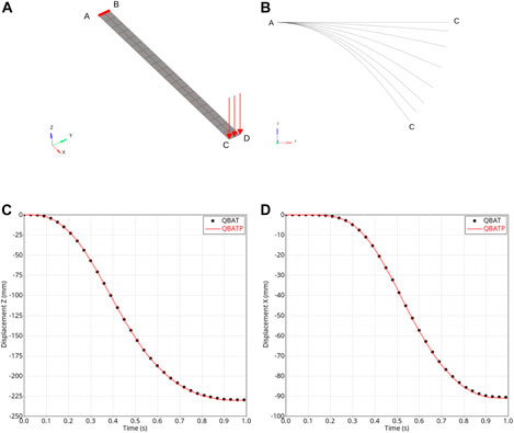
FIGURE 6. QBATP validation test: large bending of a cantilever: a comparison of solutions obtained using QBATP shells, QBAT elements and from Bisshopp and Drucker (1945), Soulat et al. (2006). (A) Geometry and setup of the test; (B) Side view of the evolution of the deformed shape of the cantilever; (C) Comparison of the evolution of the Z displacement (mm) of point C; (D) Comparison of the evolution of the X displacement (mm) of point C.
3.7.3 Non-uniform pinching pressure test
In a typical consolidation process, it can often occur that some regions undergo much higher consolidation than others. The objective of this test is to simulate this scenario which has been done by applying the pinching pressure only on one part of the model and the results are compared with the BRICK8 element. The model under consideration is exactly the same as in Section 3.7.1, i.e., the uniform crushing under pressure test, except the application of the pinching pressure. In this test, a linearly increasing pinching pressure (from 0 and up to 10,000 MPa) was applied only on the elements highlighted in red color (Figure 7A). The displacement field in Y (mm) for both BRICK8 and QBATP meshes shows a good match (Figure 7B). Furthermore, the evolution of pinching displacements (Z) for nodes N1-N4 (refer to Figure 7A for their locations) was compared with the BRICK8 model (Figure 7C) which show a good correlation. The slight difference between the displacements is due to the difference between the mid-surface normals (used to apply the pinching pressure load for QBATP elements) and the top-surface normals (used for applying the pressure load for BRICK8 elements).
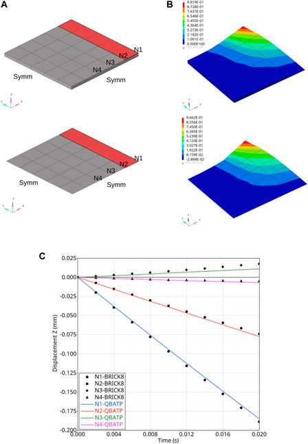
FIGURE 7. QBATP validation test: nonuniform pinching pressure: a comparison of solutions obtained using QBATP shells and BRICK8 elements. (A) Geometry, mesh and setup of the test; (B) Comparison of the final deformed shape (scaled 10X) and Y displacement field (mm); (C) Comparison of the Z (pinching direction) displacement field (mm) at nodes N1–N4.
Based on the tests discussed in this section along with several other tests discussed in Mulye (2021) and in the Supplementary Material (Section 5) of this article, it can be concluded that the QBATP element can be considered as a suitable candidate to model forming and consolidation in a unified manner.
4 Elasto-plastic constitutive model compatible with the pinching shell
This section focuses on the development of a constitutive model for the nearly incompressible thermoplastic melt polymer which is a key ingredient in the numerical modeling of the consolidation phase.
The transverse squeeze flow behavior occurring during the consolidation is predominantly governed by the nearly incompressible melt polymer. As stated in Bussetta and Correia (2018), a thermoplastic polymer behaves as a visco-elastic material at room temperature and as a visco-plastic material at higher temperature. Various modeling strategies for the behavior of polymer described in the literature can be classified into two main categories; one is followed by the composite forming community whereas a different approach is followed by the consolidation and rheology community.
An isotropic-viscoelastic constitutive model was used in Cherouat and Billoët (2001) to model the behavior of the polymer where a membrane element was used for its modeling. Using a micro-mechanical approach and without explicitly modeling fibres and matrix separately (Harrison et al., 2002); used a constitutive model for prepregs which was based on the viscosity of matrix, weave pattern and initial spacing between fibres. Polypropylene polymer was modeled using a Maxwell model in Willems et al. (2006) and the dependence of viscosity on strain rate was modeled using a power law. It was observed that simulation tests with viscosity and without viscosity resulted in a very small difference in terms of deformation. Based on this observation the simulation performed in Vanclooster et al. (2009) did not consider the matrix viscosity. Similarly, viscous effects were not considered in Khan et al. (2015), Gong et al. (2016), Gong et al. (2018) even though they used elastic, anisotropic hyperelastic and neo-hookean constitutive models for the polymer respectively. In this broad category of modeling the behavior of melt polymer for forming applications, many researchers have demonstrated that the viscous effects of the matrix can be neglected in the simulation without significantly impacting the final results. On the contrary, several works have been published where the viscous effects were modeled and their influence was investigated for shear (Haanappel et al., 2014; Machado et al., 2016) and bending (Alshahrani and Hojjati, 2017; Dörr et al., 2017b).
Even though there have been several attempts at modeling the consolidation behavior for a woven prepreg, the literature for the UD prepregs is predominantly focused on the modeling of squeeze flow phenomenon. The research focused on the modeling of transverse squeeze flow relies on the idea that a thermoplastic UD prepreg behaves as a continuum that can be modeled with a Transversely Isotropic Fluid (TIF) model (Rogers, 1989). This modeling approach is known as the “Ideal Fibre Reinforced fluid Model” (IFRM) approach. Finite element analysis using this technique was performed with the assumption of plane stress resulting in a 2D scenario in O’Bradaigh and Pipes (1991). Simulations on a full three dimensional model were performed in Sorba et al. (2017) along with the explicit modeling of the interfacial resin-rich layer.
Based on the literature review, it appears that there is no standardized approach to its modeling probably due to the complexities and challenges involved in its characterization. With this in mind, several modeling choices are made in this work that not only simplify the numerical aspects of the modeling but also reduce the complexity in the characterization procedure. They are discussed below:
• Following the approach predominantly used by composite forming community; viscous effects are not modeled within the prepreg. A plasticity-based approach is chosen in order to emulate the flow of melt polymer. For processes like QSP®, modeling the irreversibility with large deformation along with a failure criteria (which could be developed in the future) is more important than modeling the viscous effects. This is because if the UD patches experience any kind of severe loading along the direction orthogonal to fibres, they can fail. Thus plasticity has been given a preference in terms of modeling compared to viscous effects. The viscous effects could be further added to this model in the future.
• The core idea of modeling the squeeze flow based on the IFRM model is to model the prepreg as an equivalent single continuum without differentiating between polymer and fibres, which automatically includes the coupling between the two phases. In this work, this interaction is achieved by overlapping two shell elements (one for polymer and one for fibres) with shared and coincident nodes.
The modeling strategy followed in this work is as follows: each ply contains two shell element components with shared coincident nodes. One of these two components represents fibres whereas the other represents polymer. The shell for fibres is modeled using a full integration standard shell element (QBAT) of Altair Radioss™ and uses an anisotropic elastic material model (Law-58). On the other hand, the shell for polymer is modeled using the full integration pinching shell element (QBATP) developed in the previous section and shall use an elasto-plastic constitutive model (referred to as Law-91) that will be discussed next.
4.1 Global plasticity for a pinching shell
In order to model the behavior of the nearly incompressible melt polymer during consolidation; a new elasto-plastic constitutive model has been developed that is compatible with the QBATP shell element. This is inspired from the global plasticity model proposed by Ilyushin (Ilyushin, 1948) for classical shells. The Von-Mises yield criterion (f) is defined directly in terms of deviatoric stress resultants
The model uses linear isotropic hardening with radial return and a linear equation of state is used to correlate pressure, specific volume and bulk modulus. Selective reduced integration is performed for the spherical part of stress in order to avoid volumetric locking.
Also note that, the following assumptions are made (for the sake of simplicity) in the development of this model.
• For the criterion, the coupling term of the membrane and bending part is not considered. For the locations that are undergoing consolidation, it is reasonable to assume that they would be predominantly under a membrane (non-bending) stress state rather than a bending stress state thereby justifying the choice of neglecting the coupling term.
• The contribution of transverse shear is also not considered in the criterion. Thus, the resultants Nyz and Nxz are always updated assuming elastic behavior. This is not a strong assumption, since for thin shells it has been shown in Dujc and Brank (2012) that the results obtained by considering the elastic response for transverse shear showed no significant difference when plasticity was considered for transverse shear.
4.2 Algorithm
Using the modified yield criterion for pinching shell, the step by step algorithm is given below:
1. Calculate the deviatoric part of resultant of normal stresses
2. Calculate a trial deviatoric stress resultant
3. Calculate other trial stress resultants
4. Calculate Pn+1 assuming a linear equation of state (g) and performing a selective reduced integration to avoid volumetric locking (K is the bulk modulus).
5. Calculate the updated yield stress based on the equivalent plastic strain and hardening modulus (HM) as,
6. Calculate the modified yield criterion calculated in Eq. 25.
7. If f ≤ 0, it implies that the material is not undergoing plastic loading signifying
8. If f > 0, it means that the material is undergoing plastic loading. Thus, a factor for radial return (R) needs to be calculated with subsequent updates in the stress resultants, stress couples and equivalent plastic strain.
4.3 Validation
Even though only one of the numerical validations tests is discussed in this section, other numerical tests can be found in Mulye (2021).
The objective of this test is to replicate a benchmark test from Dujc and Brank (2012) consisting of a hollow cylinder with elastic perfectly plastic material properties undergoing large shear. In this test, a hollow cylinder of radius r = 285 mm, height H = 850 mm and thickness h = 5 mm undergoes shear loading (Figure 8A). The lower edge was fixed in all degrees of freedom and an imposed velocity was applied on the top edge in Y direction until a displacement of 100 mm is reached (Figure 8B). All other DoFs on this edge were constrained. The material properties were set to: E = 210,000 MPa,
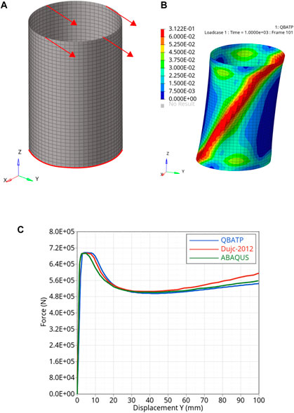
FIGURE 8. QBATP element with elasto-plastic constitutive model validation test: cylinder under shear loading: a comparison of solutions obtained using QBATP shells, ABAQUS and from Dujc and Brank (2012). (A) Geometry, mesh and setup of the test; (B) Visualization of the deformation and the equivalent plastic strain field
With this validation test along with the several other tests described in Mulye (2021), it was considered that the constitutive model has been validated.
4.4 Characterization of the constitutive model
This constitutive model requires four parameters: Young’s modulus (E), Poisson’s ratio
where Vp is the specific volume of polymer, T is the temperature, P is the pressure and other variables (B(T) and C(T)) are material parameters. The material parameters for PA-66 polymer tabulated in Table 1 in Wang et al. (1992) were used. The parameters are: C(T) = 0.0894, Vp(T, 0) = 0.7657e0.00066T and B(T) = 3226e−0.00504E−3T. Further, by assuming a linear equation of state and assuming an isothermal process; the bulk modulus of the polymer (K) was found to be 226.46 MPa. In future work, these assumptions can be resolved by implementing a specific and temperature dependent equation of state. The incompressibility of melt polymer is the motivating factor to use Poisson’s ratio
To obtain the remaining two material parameters yield stress
It is worth mentioning that an attempt was made to use a Digital Image Correlation technique was attempted by marking an initial grid on the specimen so that the local deformations could be studied. However, due to the squeeze flow occurring at such a high temperature, the markings were spread thereby making it impossible to study local deformations with this approach.
The workflow for the characterization procedure is shown in Figure 9. The stack of UD prepregs undergoes consolidation in the flat sections of the mold. A schematic representation of the temperature and loading cycles is shown in. After the completion of the consolidation experiment, one can measure the final average thickness and final maximum width using the deformed shape of the sample.
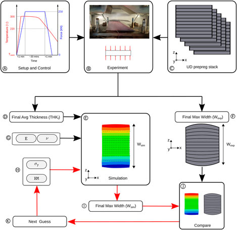
FIGURE 9. A schematic representation of the characterization strategy for the four material parameters of the elasto-plastic constitutive model.
Due to the use of the industrial hydraulic press, this is representative of industrial conditions. Thus neither the accurate compaction force nor the punch displacement can be controlled during the test. This also is a typical situation in the industrial setups where these quantities cannot be controlled or measured very precisely. Thus, the characterization strategy was planned solely based on the final deformed shape after consolidation.
The final deformed shape can be subdivided into two quantities: out of plane deformation (thickness reduction) and in-plane deformation (increase of width and length due to the transverse squeeze flow). These two are the only outputs needed for the characterization method proposed here.
4.5 Experimental procedure
The characterization in this work is carried out on UD plies. The UD ply tapes used in this work consist of Glass fibres impregnated with PA-66 polymer (Vf = 60%). The specification for the same is given by Celestran® CFR-TP PA-66 GF60-02 (Supplier: TICONA). The experimental campaign on a stack of UD prepregs with a configuration
Referring back to Figure 9, the value of the final average thickness serves as an input to the simulation. Also, the material parameters obtained using Tait equation and incompressibility condition (E and
4.6 Consolidation process modeling of thermoplastic UD prepregs
In this section, various test cases of consolidation of UD thermoplastic prepregs are discussed with the aim to demonstrate the capabilities of using the elasto-plastic constitutive model developed in this work along with the QBATP element in order to do consolidation process modeling.
4.6.1 Flat [0°]5 case
Even though the characterization of constitutive model was carried out using this prepreg stack configuration; only the maximum final width of the specimen was used for the characterization. Thus, it is interesting to observe the overall final shape and to compare that with the experimental observations.
For the simulation, a flat UD ply of dimensions 60 mm × 60 mm and a thickness of 1.55 mm was modeled between two flat molds. The punch and die are given elastic material properties. The summary of the material properties used for this simulation is given in the Supplementary Material (Section 3). An imposed displacement is applied on the flat punch which induces a transverse squeeze flow in the prepreg stack whereas the die is fixed in all DoFs. The simulation is run until a final average thickness of 1.161 mm was obtained which corresponds to a total consolidation of 25.1%. The displacement field along direction Z at various stages of the consolidation is shown in Figure 10. The final deformed shape obtained from the simulation is compared to the experiment in Figure 11A. Fibres being nearly inextensible, the displacements along X are very small as indicated by the measurements at various locations. It can be observed that even though some curvature is seen in the simulation depicting the barreling effect, it does not match exactly with the experiment. This difference could have come from the ply-mold interaction and the heat transfer happening at their interface which is not modeled in the simulation.
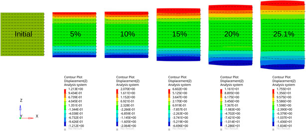
FIGURE 10. Deformation of a flat [0°]5 stack undergoing various degrees of consolidation (5%–25.1%).
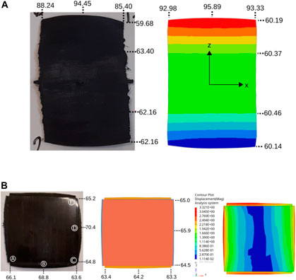
FIGURE 11. Comparison of the numerical simulation and experimental observations for (A) a flat unidirectional [0°]5 stack; (B) a flat [0°/90°]2 stack (numbers indicate the dimensions measured at various locations of the stack).
4.6.2 Flat [0°/90°]5 case
Another consolidation experimental test is conducted with a stack of the configuration
The in-plane deformations observed from the simulations are compared with those obtained from the experiments in Figure 11B. The width predictions at the corners (locations, and are predicted quite well from the simulation (with a difference of less than 1 mm). Also, the deformation patterns at the corners are predicted with a good accuracy. However, the amount of widening predicted by the simulation at the midpoints of sides of the stack (locations and) is less than what has been observed in the experiments. A further investigations both from the point of view of numerical and experimental work can be helpful in identifying and resolving the differences observed in the results of the simulation and the experiment. As discussed in Sorba et al. (2017), the presence of a thin polymer layer at the interface in cross-ply stacks enhances layer spreading.
5 Unified numerical process modeling of forming and consolidation
With all the above ingredients (i.e., QBATP shell element and elasto-plastc constitutive model for melt polymer) implemented and validated, one can attempt to perform a unified numerical process simulation of forming and consolidation. In addition to the modeling strategy discussed already, the ply-ply interaction is modeled with Type-25 contact law in Altair RadiossTM with interply adhesion as discussed in Mulye et al. (2020).
5.1 Unified approach testing and validation
The objective of this section is to use all the novel pinching shell element, elasto-plastic constitutive model for pinching shell coupled with the interply adhesion in order to test the unified approach to model both forming and consolidation flow. This has been done for the following two cases.
5.1.1 Revisiting the industrial model from CETIM
In this section, the industrial model from CETIM discussed previously in Mulye et al. (2020) is revisited but with the updated modeling strategy that consists of using the QBATP element with the elasto-plastic constitutive model. Note that in Mulye et al. (2020), only the forming phase was simulated using the classical shell elements.
The considered industrial model (Figure 12) has a prepreg stack consisting of 9 plies of different shapes, fibre architectures (UD/woven) and fibre orientations. The woven prepreg plies are TEPEX® dynalite 101-RG600(x) (Supplier: BONDLAMINATES). The UD ply tapes are Celestran® CFR-TP PA-66 GF60-02 (Supplier: TICONA). A mesh size of 4 mm was used which generated a total 29,653 nodes consisting of 48,404 quadrilateral elements. The material parameters and parameters related to the interply adhesion are taken from Mulye et al. (2020). In terms of computational time for simulating this model, it took about 2 h with 4 threads with shared memory processing on a local computer [Intel(R) Xeon(R) CPU E3-1545M v5 @ 2.90GHz (x86_64)] with the natural time-step of the model.
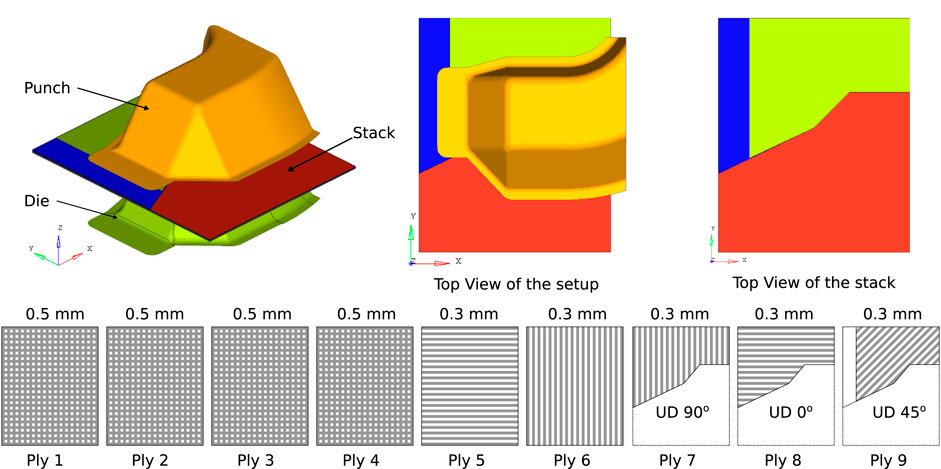
FIGURE 12. Numerical model of the industrial component designed by CETIM showing its geometry and the prepreg stack configuration (Ply 1 to 9: from bottom to the top of the stack).
Overall, with reference to the final deformed shape, the results of simulation with unified approach were found to be comparable with the ones obtained from the experiment (refer to the Section 6 in Supplementary Material to see a qualitative comparison between the two). However, now with this new unified approach, one now has access to additional information such as the through-thickness normal stress.
The maximum initial stack thickness is 3.5 mm. Thus, a rough estimate can be made to predict that the consolidation phase will begin when the distance between the punch and die reduces to 3.5 mm (after adjusting for the thicknesses of die and punch themselves). Based on this prediction, the transverse normal stress for all plies was plotted along with the magnitude of contact force experienced by the punch at various instants during the simulation. Figure 13A is obtained when the punch-die distance is 4.78 mm which is before the beginning of the consolidation as per estimate. As expected, there is neither a noticeable σzz nor any contact force on the flat portions of the punch. After the consolidation begins, one should observe the development of a through-thickness stress in the regions which undergo consolidation. As a consequence, one should observe a reaction force on the punch in that region. This was observed in the Figure 13B. As the consolidation phase continues further, the stress field intensifies and spreads into other regions as more regions come in contact with the molds and begin experiencing consolidation pressure. Finally, at the end of consolidation phase; Figure 13C shows the state of the stress and reaction force. At this stage, the distance between the die and punch is 3.22 mm (which amounts to
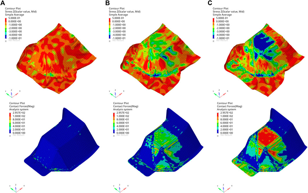
FIGURE 13. Results of the unified numerical simulation of the forming and consolidation for QSP®: Field of the transverse normal stress σzz in MPa (top) and field of the magnitude of the contact force in N on the punch (bottom): (A) Before consolidation phase begins; (B) During the consolidation phase; (C) After the consolidation phase (final state).
As expected, it can be seen that the maximum compressive stress is on the flat section of the top face of the component. Whereas, other regions are contributing less in the sharing of the consolidation pressure. This can be qualitatively cross-verified with the observed contact force plot. Ply-wise through-thickness normal stress is an important information which can be used in the design of the mold and/or stack. This helps in identifying which regions will have a poor quality of consolidation. The regions with lower consolidation are likely to have higher porosities and therefore are possible sites of weakness/failure for the component. Thus, based on the information obtained from this type of simulation, one can either modify the mold design or the stack itself, in order to have a better consolidation behavior.
Similar to the exercise performed in Mulye et al. (2020), the fibre orientations after the simulations using the unified approach were compared at various locations with those obtained from the experiments. The fibre orientations obtained from the unified simulation approach are listed in the Supplementary Material (Section 4). Even though a detailed analysis of the comparison can be found in Mulye (2021); overall when compared for all faces, the fibre orientations predicted by the unified simulation were on an average 5.4° away from the experiments. This value is similar to the value obtained with a pure forming solution (which was 5.9° degrees).
This verification is essential since there are several changes in the modeling approach for the forming approach compared to the unified approach such as the usage of QBATP elements with elasto-plastic constitutive model and other consequences of the pinching behavior both within the components as well as at the interfaces.
It is perhaps expected that in this component, there is not much of a squeeze flow to be observed because of mainly two reasons. First, the compressive loading predominantly passed through a zone on the top face (Figure 13C). Second, due to the overall stack configuration, there may not be enough room for the squeeze flow to occur. This may not be the case with other components and stacking sequences. An example designed to show the squeeze flow on a semi-industrial component is discussed next.
5.1.2 Numerical simulation of a UD ply
To validate this unified approach, a semi-industrial model designed by CETIM was considered. It consists of a flat UD ply stack [0°]4 of dimensions 420 mm × 60 mm and thickness of 0.31 mm each resulting in a total stack thickness of 1.24 mm. The fibres are oriented along the X direction (Figure 14A). The UD ply tapes used in this work consist of Glass fibres impregnated with PA-66 polymer Celestran® CFR-TP PA-66 GF60-02 (Supplier: TICONA). The unified numerical simulation consisting of 6,000 deformable shell elements took around 10 min on a local computer [Intel(R) Xeon(R) CPU E3-1545M v5 @ 2.90GHz (x86_64)] using the natural time-step of the model.
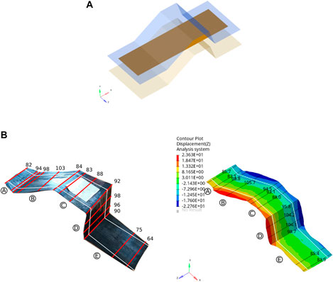
FIGURE 14. Experimental validation of the unified numerical simulation of a unidirectional ply on Omega mold: (A) Geometry, setup and mesh; (B) Width comparison between experiments and the numerical simulation results (measurements are in mm and the initial width is shown with the white lines).
In order to quantitatively compare the results of the unified forming and consolidation simulation with the experiments, the final widths (in mm) were measured at various locations of the ply in both experiments and simulation (Figure 14B). Ideally it would have been interesting to compare the field of the displacement/strains in the ply using Digital Image Correlation (DIC) technique. We tried to mark the grid on the initial ply before it undergoes consolidation in order to perform a DIC during or after consolidation. However, because of the squeeze-flow these marked lines spread (turning into a patch of paint). So it becomes nearly impossible to perform DIC on such a sample. Therefore, we have chosen to measure dimensions at several locations and compare them with the simulation. Since, the ply thickness is what is controlled in the simulation (through the application of imposed displacement on the punch), and because there is no significant change in the dimensions along the fibre directions; only the width measurements from the simulation at various locations were compared to the experimental measurements.
Based on the comparison, several observations can be made. With the exception of face, all other faces have better results. Considering all faces, the average of absolute errors in the widths calculated from simulation and obtained from the experiments was found to be 7.1 mm. Also, the maximum width predicted by the simulation is 105.7 mm (on face) which is close to the experimentally observed value which is 103 mm.
There are several possible hypotheses that can explain the difference of results on face such as, 1) thermal effects such as the temperature inhomogeneity in the mold 2) geometrical effects such as imperfect parallelism of the mold 3) process related effects such as a possible local deformations (bending) of the mold itself.
In summary, the two validation tests presented above show that the simulation using the unified approach are able to model the squeeze flow behavior. It is also able to predict the final deformed shape with a reasonable accuracy with this modeling approach.
6 Application: improving the mold and part design
This section demonstrates how the unified simulation strategy for forming and consolidation (when included in the iterative design pipeline) can help in improving the mold design for thermoplastic composites. To show the iterative design process for this demonstrative example, the geometry of punch was locally modified by translating nodes normal to their plane using Hypermesh. The modifications are done based on the observed deformations from simulation. The original design (Section 5.1.2) is referred to here as Design-1 shown in Figure 15A. Recalling that the consolidation was found to occur only in zones, and. On the other hand, the zones and experienced no noticeable consolidation.
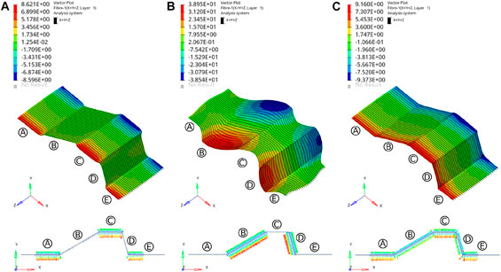
FIGURE 15. Iterative design change in the mold geometry with the use of a unified numerical process modeling of forming and consolidation: field of the Z displacement in mm (top) and reaction force distribution (bottom) for: (A) Design-1; (B) Design-2; (C) Design-3.
Based on this observation, the nodes on faces and of the punch were moved inwards (orthogonally to the face) by a small distance of about 0.6 mm (which was later found to be significant) to arrive at Design-2. The simulation outcomes of Design-2 are shown in Figure 15B. It showed the exact opposite trend as that of Design-1. The consolidation was found to occur in zones and whereas the other zones, and showed no significant consolidation. Again, this is evident from the reaction force distribution plot (Figure 15B). This provided an indication that for a good consolidation in all zones, the geometry of the punch should be somewhere in between Design-1 and Design-2.
Also, an important observation can be made with respect to the fibre orientation distribution for various designs. By tuning the mold design and thereby tweaking the amount of squeeze flow occurring in each zone, it was possible to maintain the straightness of the fibres in case of Design-3 which was not possible with the initial designs Design-1 and Design-2 where the local barreling type effect made significant changes in the fibre orientations.
Based on this conclusion, Design-3 was created this time by moving the nodes on faces and by 0.1 mm with respect to the Design-1. The simulation on this design, showed a relatively uniform distribution of consolidation on all faces as shown in Figure 15C.
This demonstrates how the unified solution proposed in this work can help the manufacturers to design better tooling based on the outcomes of the numerical process simulation that considers forming, consolidation and potential transverse squeeze flow in order to achieve a desired product quality and part design.
7 Conclusion
In summary, it has been shown that the simulation of forming and consolidation phases of QSP® can be performed using a shell element based unified approach. With the use of the novel pinching shell element (QBATP) and the elasto-plastic constitutive model for the melt polymer (based on four parameters); one can simulate and predict the squeeze flow behavior with a reasonable accuracy. Additionally due to the use of pinching shell elements in this approach; one has access to additional ply level information such as transverse normal stress which can be used to design the mold and/or the stack itself by incorporating the effects of the consolidation phase together with the forming phase.
Data availability statement
The original contributions presented in the study are included in the article/Supplementary Material, further inquiries can be directed to the corresponding author.
Author contributions
LM and CB contributed to the conceptualization of this work. LM and AL were involved in the methodology. PM worked on the development of the software with a guidance from LM. SC-C led the experimental campaign in this work. The formal analysis, investigation and writing was carried out by PM. This was supervised by LM, CB, and SC-C. DG provided resources which include previous experimental data and equipment from CETIM. All authors contributed to the article and approved the submitted version.
Funding
The authors would like to express their gratitude towards ANRT (CIFRE 2017/1621) for the financial support.
Conflict of interest
PM and LM were employed by Altair Engineering France.
The remaining authors declare that the research was conducted in the absence of any commercial or financial relationships that could be construed as a potential conflict of interest.
Publisher’s note
All claims expressed in this article are solely those of the authors and do not necessarily represent those of their affiliated organizations, or those of the publisher, the editors and the reviewers. Any product that may be evaluated in this article, or claim that may be made by its manufacturer, is not guaranteed or endorsed by the publisher.
Supplementary material
The Supplementary Material for this article can be found online at: https://www.frontiersin.org/articles/10.3389/fmats.2023.1176482/full#supplementary-material
References
Alshahrani, H., and Hojjati, M. (2017). Bending behavior of multilayered textile composite prepregs: Experiment and finite element modeling. Mater. Des.124, 211–224. doi:10.1016/j.matdes.2017.03.077
Altair Engineering (2022). OpenRadioss source code. Available at: https://github.com/OpenRadioss/OpenRadioss.
Bathe, K., Ramm, E., and Wilson, E. (1975). Finite element formulations for large deformation dynamic analysis. Int. J. Numer. methods Eng.9, 353–386. doi:10.1002/nme.1620090207
Batoz, J., and Dhatt, G. (1992). Modélisation des structures par éléments finis, Paris: Coques. Hermès.
Belnoue, J.-H., Nixon-Pearson, O., Ivanov, D., and Hallett, S. (2016). A novel hyper-viscoelastic model for consolidation of toughened prepregs under processing conditions. Mech. Mater.97, 118–134. doi:10.1016/j.mechmat.2016.02.019
Belnoue, J.-H., Nixon-Pearson, O., Thompson, A., Ivanov, D., Potter, K., and Hallett, S. (2018). Consolidation-driven defect generation in thick composite parts. J. Manuf. Sci. Eng.140, 071006. doi:10.1115/1.4039555
Belytschko, T., Liu, W., Moran, B., and Elkhodary, K. (2013). Nonlinear finite elements for continua and structures. United States: John Wiley & Sons.
Bischoff, M., and Ramm, E. (2000). On the physical significance of higher order kinematic and static variables in a three-dimensional shell formulation. Int. J. Solids Struct.37, 6933–6960. doi:10.1016/s0020-7683(99)00321-2
Bischoff, M., and Ramm, E. (1997). Shear deformable shell elements for large strains and rotations. Int. J. Numer. Methods Eng.40, 4427–4449. doi:10.1002/(sici)1097-0207(19971215)40:23<4427::aid-nme268>3.0.co;2-9
Bisshopp, K., and Drucker, D. (1945). Large deflection of cantilever beams. Q. Appl. Math.3, 272–275. doi:10.1090/qam/13360
Boisse, P., Akkerman, R., Carlone, P., Kärger, L., Lomov, S. V., and Sherwood, J. A. (2022). Advances in composite forming through 25 years of esaform. Int. J. Material Form.15, 39. doi:10.1007/s12289-022-01682-8
Brank, B., Korelc, J., and Ibrahimbegović, A. (2002). Nonlinear shell problem formulation accounting for through-the-thickness stretching and its finite element implementation. Comput. Struct.80, 699–717. doi:10.1016/s0045-7949(02)00042-1
Büchter, N., and Ramm, E. (1992). 3d-extension of nonlinear shell equations based on the enhanced assumed strain concept. Comput. Methods Appl. Sci.1992, 55–62.
Büchter, N., Ramm, E., and Roehl, D. (1994). Three-dimensional extension of non-linear shell formulation based on the enhanced assumed strain concept. Int. J. Numer. methods Eng.37, 2551–2568. doi:10.1002/nme.1620371504
Bussetta, P., and Correia, N. (2018). Numerical forming of continuous fibre reinforced composite material: A review. Compos. Part A Appl. Sci. Manuf.113, 12–31. doi:10.1016/j.compositesa.2018.07.010
Cherouat, A., and Billoët, J. (2001). Mechanical and numerical modelling of composite manufacturing processes deep-drawing and laying-up of thin pre-impregnated woven fabrics. J. Mater. Process. Technol.118, 460–471. doi:10.1016/s0924-0136(01)00987-6
Cocchetti, G., Pagani, M., and Perego, U. (2013). Selective mass scaling and critical time-step estimate for explicit dynamics analyses with solid-shell elements. Comput. Struct.127, 39–52. doi:10.1016/j.compstruc.2012.10.021
Dia, M., Hamila, N., Abbas, M., and Gravouil, A. (2020). A nine nodes solid-shell finite element with enhanced pinching stress. Comput. Mech.65, 1377–1395. doi:10.1007/s00466-020-01825-1
Dörr, D., Brymerski, W., Ropers, S., Leutz, D., Joppich, T., Kärger, L., et al. (2017a). A benchmark study of finite element codes for forming simulation of thermoplastic ud-tapes. Procedia CIRP66, 101–106. doi:10.1016/j.procir.2017.03.223
Dörr, D., Schirmaier, F. J., Henning, F., and Kärger, L. (2017b). A viscoelastic approach for modeling bending behavior in finite element forming simulation of continuously fiber reinforced composites. Compos. Part A Appl. Sci. Manuf.94, 113–123. doi:10.1016/j.compositesa.2016.11.027
Dujc, J., and Brank, B. (2012). Stress resultant plasticity for shells revisited. Comput. Methods Appl. Mech. Eng.247, 146–165. doi:10.1016/j.cma.2012.07.012
Dvorkin, E., and Bathe, K. (1984). A continuum mechanics based four-node shell element for general non-linear analysis. Eng. Comput.1, 77–88. doi:10.1108/eb023562
Gong, Y., Peng, X., Yao, Y., and Guo, Z. (2016). An anisotropic hyperelastic constitutive model for thermoplastic woven composite prepregs. Compos. Sci. Technol.128, 17–24. doi:10.1016/j.compscitech.2016.03.005
Gong, Y., Xu, P., Peng, X., Wei, R., Yao, Y., and Zhao, K. (2018). A lamination model for forming simulation of woven fabric reinforced thermoplastic prepregs. Compos. Struct.196, 89–95. doi:10.1016/j.compstruct.2018.05.004
Guillon, D., Lemasçon, A., and Callens, C. (2016). “QSP®: An innovative process based on tailored preforms for low cost and fast production of optimized thermoplastic composite parts,” in Proceedings of the 17th European Conference on Composite Materials ECCM17, Munich, Germany, 26-30th June 2016.
Haanappel, S., Ten Thije, R., Sachs, U., Rietman, B., and Akkerman, R. (2014). Formability analyses of uni-directional and textile reinforced thermoplastics. Compos. Part A Appl. Sci. Manuf.56, 80–92. doi:10.1016/j.compositesa.2013.09.009
Harrison, P., Clifford, M., Long, A., and Rudd, C. (2002). Constitutive modelling of impregnated continuous fibre reinforced composites micromechanical approach. Plastics, Rubber Compos.31, 76–86. doi:10.1179/146580102225001409
Hughes, T., and Tezduyar, T. (1981). Finite elements based upon mindlin plate theory with particular reference to the four-node bilinear isoparametric element. J. Appl. Mech.48, 587–596. doi:10.1115/1.3157679
Irisarri, F., Macquart, T., Julien, C., and Espinassou, D. (2019). A novel design method for the fast and cost-effective manufacture of composite parts employing the quilted stratum process. Compos. Part B Eng.158, 364–372. doi:10.1016/j.compositesb.2018.09.070
Khan, M., Reynolds, N., Williams, G., and Kendall, K. (2015). Processing of thermoset prepregs for high-volume applications and their numerical analysis using superimposed finite elements. Compos. Struct.131, 917–926. doi:10.1016/j.compstruct.2015.06.056
Lim, T., and Ramakrishna, S. (2002). Modelling of composite sheet forming: A review. Compos. Part A Appl. Sci. Manuf.33, 515–537. doi:10.1016/s1359-835x(01)00138-5
Machado, M., Fischlschweiger, M., and Major, Z. (2016). A rate-dependent non-orthogonal constitutive model for describing shear behaviour of woven reinforced thermoplastic composites. Compos. Part A Appl. Sci. Manuf.80, 194–203. doi:10.1016/j.compositesa.2015.10.028
Mulye, P. D. (2021). “Unified numerical modeling of forming and consolidation of thermoplastic composites with prepreg patches,” (France: École centrale de Nantes). Ph.D. thesis.
Mulye, P., Hemmer, J., Morançay, L., Binetruy, C., Leygue, A., Comas-Cardona, S., et al. (2020). Numerical modeling of interply adhesion in composite forming of viscous discontinuous thermoplastic prepregs. Compos. Part B Eng.191, 107953. doi:10.1016/j.compositesb.2020.107953
O’Bradaigh, C., and Pipes, B. (1991). Finite element analysis of composite sheet-forming process. Compos. Manuf.2, 161–170. doi:10.1016/0956-7143(91)90135-4
Olovsson, L., Unosson, M., and Simonsson, K. (2004). Selective mass scaling for thin walled structures modeled with tri-linear solid elements. Comput. Mech.34, 134–136. doi:10.1007/s00466-004-0560-6
Oñate, E. (2013). Structural analysis with the finite element method. Linear statics: Volume 2: Beams, plates and shells. Berlin, Germany: Springer Science & Business Media.
Parisch, H. (1991). An investigation of a finite rotation four node assumed strain shell element. Int. J. Numer. Methods Eng.31, 127–150. doi:10.1002/nme.1620310108
Rogers, T. (1989). Squeezing flow of fibre-reinforced viscous fluids. J. Eng. Math.23, 81–89. doi:10.1007/bf00058434
Sansour, C., and Bufler, H. (1992). An exact finite rotation shell theory, its mixed variational formulation and its finite element implementation. Int. J. Numer. Methods Eng.34, 73–115. doi:10.1002/nme.1620340107
Schäfer, B., Dörr, D., and Kärger, L. (2021). “Potential and challenges of a solid-shell element for the macroscopic forming simulation of engineering textiles,” in ESAFORM 2021 - 24th International Conference on Material Forming, Online event, 14 Apr 2021 → 16 Apr 2021. doi:10.25518/esaform21.883
Schäfer, B., Dörr, D., and Kärger, L. (2020). Reduced-integrated 8-node hexahedral solid-shell element for the macroscopic forming simulation of continuous fibre-reinforced polymers. Procedia Manuf.47, 134–139. doi:10.1016/j.promfg.2020.04.154
Schell, J., Amory, L., and Guillon, D. (2016). Movement of patches during thermoforming: Experiment and simulation. AIP Conf. Proc.1769, 170032.
Schwarze, M., and Reese, S. (2011). A reduced integration solid-shell finite element based on the eas and the ans concept—Large deformation problems. Int. J. Numer. Methods Eng.85, 289–329. doi:10.1002/nme.2966
Simo, J., and Rifai, M. (1990). A class of mixed assumed strain methods and the method of incompatible modes. Int. J. Numer. methods Eng.29, 1595–1638. doi:10.1002/nme.1620290802
Simo, J., Rifai, M., and Fox, D. (1990). On a stress resultant geometrically exact shell model. part iv: Variable thickness shells with through-the-thickness stretching. Comput. methods Appl. Mech. Eng.81, 91–126. doi:10.1016/0045-7825(90)90143-a
Sorba, G., Binetruy, C., Leygue, A., and Comas-Cardona, S. (2017). Squeeze flow in heterogeneous unidirectional discontinuous viscous prepreg laminates: Experimental measurement and 3d modeling. Compos. Part A Appl. Sci. Manuf.103, 196–207. doi:10.1016/j.compositesa.2017.10.007
Sorba, G. (2017). “Experimental study and numerical modelling of squeeze flow in laminate viscous discontinuous composites,” (France: École centrale de Nantes). Ph.D. thesis.
Soulat, D., Cheruet, A., and Boisse, P. (2006). Simulation of continuous fibre reinforced thermoplastic forming using a shell finite element with transverse stress. Comput. Struct.84, 888–903. doi:10.1016/j.compstruc.2006.02.011
Thomas J, P. P., and Charlotte, L. (2019). “Process simulation to assist in the design of a tp composite window frame,” in SAMPE Europe Conference, Madrid, Spain, 3 – 5 October 2023.
Vanclooster, K., Lomov, S., and Verpoest, I. (2009). Experimental validation of forming simulations of fabric reinforced polymers using an unsymmetrical mould configuration. Compos. Part A Appl. Sci. Manuf.40, 530–539. doi:10.1016/j.compositesa.2009.02.005
Wang, Y., Chia, W., Hsieh, K., and Tseng, H. (1992). Specific volume of molten thermoplastic polymer composite at high pressure. J. Appl. Polym. Sci.44, 1731–1736. doi:10.1002/app.1992.070441005
Willems, A., Lomov, S., Vandepitte, D., and Verpoest, I. (2006). “Double dome forming simulation of woven textile composites,” in The nineth international conference on material forming ESAFORM, Glasgow, United Kingdom, April 26-28, 2006, 747–750.
Xiong, H., Hamila, N., and Boisse, P. (2019). Consolidation modeling during thermoforming of thermoplastic composite prepregs. Materials12, 2853. doi:10.3390/ma12182853
Xiong, H., Maldonado, E., Hamila, N., and Boisse, P. (2018). A prismatic solid-shell finite element based on a dkt approach with efficient calculation of through the thickness deformation. Finite Elem. Analysis Des.151, 18–33. doi:10.1016/j.finel.2018.08.003
Keywords: process simulation, forming, consolidation, shell element, prepregs
Citation: Mulye PD, Morançay L, Binetruy C, Comas-Cardona S, Leygue A and Guillon D (2023) Unified numerical process modeling of forming and consolidation for thermoplastic composites with prepreg patches. Front. Mater. 10:1176482. doi: 10.3389/fmats.2023.1176482
Received: 28 February 2023; Accepted: 17 May 2023;
Published: 12 June 2023.
Edited by:
Chung Hae Park, IMT Lille Douai, FranceReviewed by:
Emmanuelle Vidal-Salle, Institut National des Sciences Appliquées de Lyon (INSA Lyon), FranceLuise Kärger, Karlsruhe Institute of Technology (KIT), Germany
Samir Allaoui, Université de Reims Champagne-Ardenne, France
Copyright © 2023 Mulye, Morançay, Binetruy, Comas-Cardona, Leygue and Guillon. This is an open-access article distributed under the terms of the Creative Commons Attribution License (CC BY). The use, distribution or reproduction in other forums is permitted, provided the original author(s) and the copyright owner(s) are credited and that the original publication in this journal is cited, in accordance with accepted academic practice. No use, distribution or reproduction is permitted which does not comply with these terms.
*Correspondence: P. D. Mulye, UGFyaXMtRGlsaXAuTXVseWVAZWMtbmFudGVzLmZy