 M. J. Nieves
 G. Carta
 V. Pagneux3
 M. Brun
- 1School of Computing and Mathematics, Keele University, Keele, United Kingdom
- 2Department of Mechanical, Chemical and Materials Engineering, University of Cagliari, Cagliari, Italy
- 3Laboratoire D’Acoustique de L’Université Du Maine (LAUM), Le Mans, France
We discuss the propagation of Rayleigh waves at the boundary of a semi-infinite elastic lattice connected to a system of gyroscopic spinners. We present the derivation of the analytical solution of the equations governing the system when the lattice is subjected to a force acting on the boundary. We show that the analytical results are in excellent agreement with the outcomes of independent finite element simulations. In addition, we investigate the influence of the load direction, frequency and gyroscopic properties of the model on the dynamic behavior of the micro-structured medium. The main result is that the response of the forced discrete system is not symmetric with respect to the point of application of the force when the effect of the gyroscopic spinners is taken into account. Accordingly, the gyroscopic lattice represents an important example of a non-reciprocal medium. Hence, it can be used in practical applications to split the energy coming from an external source into different contributions, propagating in different directions.
1 Introduction
According to their original definition, Rayleigh waves are a class of elastic waves that propagate on the surface of an infinite homogenous isotropic solid, and they are confined within a superficial region whose thickness is comparable with their wavelength (Rayleigh, 1885). These waves are well known by seismologists, since they are usually detected after the occurrence of an earthquake. They are also observed in other common urban activities, such as construction and demolition works and vehicular traffic, in addition to industrial processes and technologies, like mining exploration, non-destructive testing and design of electronic instruments. In the literature, they have been studied in depth especially with reference to continuous media (see, for instance, the classical treatizes by Viktorov (1967), Achenbach (1973) and Graff (1975)).
Surface waves traveling on the free boundaries of periodic media are usually referred to as Rayleigh-Bloch waves. They are of great importance in problems concerning the dynamic propagation of cracks in discrete systems, as discussed by Marder and Gross (1995) and Slepyan (2002) for uniform media and in successive works (Nieves et al., 2013) for non-uniform lattices. Similar localized phenomena may play a substantial role in non-uniform crack propagation as evidenced in (Piccolroaz et al., 2020), where lattice dissimilarity has been shown to promote or diminish localized deformations around the faces of the crack. Trapped modes associated with Rayleigh-Bloch waves in systems incorporating periodic gratings or periodic arrays of resonators were analyzed by Porter and Evans (1999), Porter and Evans (2005), Linton and McIver (2002) and Antonakakis et al. (2014) for scalar problems, by Colquitt et al. (2015) for vector systems and by Haslinger et al. (2017) and Morvaridi et al. (2018) for plates.
Recently, there has been an increasing interest in the design and fabrication of elastic media with unusual properties, often referred to as metamaterials (see the recent works by Filipov et al. (2015), Misseroni et al. (2016), Armanini et al. (2017), Bordiga et al. (2018), Bacigalupo et al. (2019), Al Ba’ba’a et al. (2020), Tallarico et al. (2020) and Wenzel et al. (2020) amongst others). In this paper, we focus the attention on an elastic metamaterial consisting of a triangular lattice connected to a system of gyroscopic spinners. The presence of gyroscopic spinners breaks the time-reversal symmetry of the system and makes the medium non-reciprocal, as proved by Nieves et al. (2020). We observe that the gyroscopic effect plays the role of magnetic bias (Bi et al., 2011) or angular momentum (Sounas et al., 2013) in linear non-reciprocal electromagnetic metamaterials and of circulating fluids in acoustic linear circulators (Fleury et al., 2014).
Firstly introduced by Brun et al. (2012) and later developed by Carta et al. (2014), a gyroscopic elastic lattice is a tunable system, whose dispersive properties can be varied by changing the spin and precession rates of the spinners. This type of metamaterial can be utilized to force waves to propagate along a line, whose direction is defined by the geometry of the medium (Carta et al., 2017). Gyroscopic spinners can also be employed to design topological insulators, where waves travel in one direction and are immune to backscattering (Nash et al., 2015; Süsstrunk and Huber, 2015; Wang et al., 2015; Garau et al., 2018; Lee et al., 2018; Mitchell et al., 2018; Carta et al., 2019; Garau et al., 2019; Carta et al., 2020). Furthermore, systems with gyroscopic spinners can be used to design coatings to hide the presence of objects in a continuous or discrete medium (Brun et al., 2012; Garau et al., 2019). In a recent work by Nieves et al. (2020), the dispersion analysis of Rayleigh waves in a semi-infinite triangular gyroscopic lattice has been carried out. The non-symmetry of the eigenmodes of the lattice’s particles at the free boundary for positive and negative values of the wave number has been linked to the non-symmetry of the system’s response to an applied force, determined by means of finite element simulations. In addition, a comparison with an effective gyroscopic continuum discussed in that paper has corroborated the results for the discrete system when low values of the wave number are considered.
In this paper, we present for the first time the analytical derivation of the displacement field in a semi-infinite elastic lattice incorporating gyroscopic spinners, focusing the attention on Rayleigh waves. Conversely, the main objective of previous papers (Garau et al., 2018, 2019) was related to the study of topologically-protected waveforms in lattices incorporating sub-domains with different values of the parameters of the gyroscopic spinners. The analytical results of the present paper are also verified with an independent finite element code. The displacement field produced by a point load acting on the boundary of the medium and the calculation of the energy flow demonstrate that the considered system is non-reciprocal, as the response of the forced lattice is not symmetric with respect to the point of application of the concentrated load. The influence of different physical quantities on the behavior of the gyroscopic system is also investigated through a detailed parametric analysis.
While in (Nieves et al., 2020) the wave field produced by a force on the boundary was determined numerically by using a finite element code, here the response of the system is calculated by means of a novel analytical formulation. The latter has many advantages. First, it does not require Adaptive Absorbing Layers (AAL) to prevent wave reflections at the boundaries of the computational domain; in fact, AAL are frequency-dependent and, as a consequence, their characteristic parameters need to be tuned manually every time the frequency is changed. The analytical formulation does not require the introduction of fictitious boundaries as in finite element codes. Second, the analytical formulation allows one to perform a parametric analysis quickly and efficiently, a task that is not straightforward in many finite element packages and that is performed here. Third, analytical results are necessary to validate the outcomes of finite element models. For these reasons, it is envisaged that the proposed analytical approach can be useful to the interested reader to tackle similar dynamic problems in discrete elastic systems.
2 Materials and Methods
The material under consideration consists of a semi-infinite two-dimensional triangular lattice of masses m, linked by elastic springs of stiffness γ, length L and whose inertia is negligible in comparison with m. The planar and three-dimensional representations of the lattice are shown in Figures 1A,C, respectively. In addition, each mass is attached to a gyroscopic spinner (see Figure 1B), whose configuration is described by the Euler angles θ, ϕ and ψ, denoted as the nutation, precession and spin angles, respectively. We assume that the nutation angle θ is small (
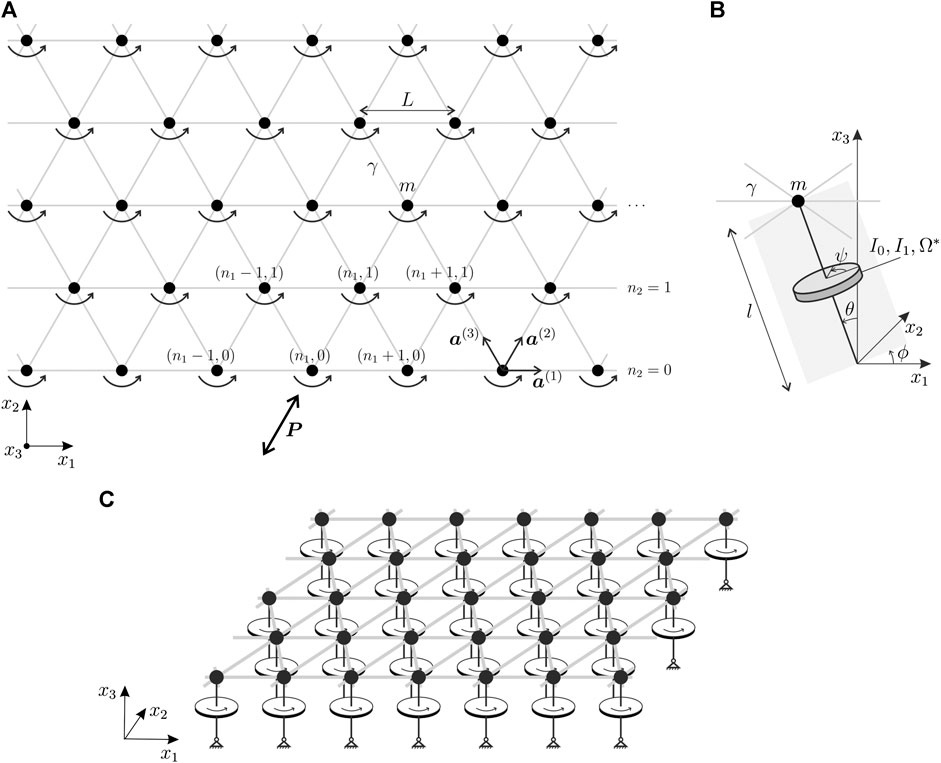
FIGURE 1. (A) Semi-infinite triangular array of masses, interconnected by elastic links and joined to gyroscopic spinners; a point force is applied on the boundary of the medium. (B) Representation of a gyroscopic spinner attached to a lattice’s mass; θ, ϕ and ψ indicate the nutation, precession and spin angles, respectively. (C) Three-dimensional sketch of the gyro-elastic lattice.
In practice, such a lattice can be realized by constructing a triangular array of masses (represented, for example, by spheres) connected by thin elastic rods. At the bottom part of each mass a cylindrical hole can be drilled, where the tip of the gyroscopic spinner can be inserted. The connection needs to be frictionless, so that the spinning motion of the gyroscope is not transmitted to the mass, which can only move in the x1- or x2‐direction without rotating. The spinning motion of the gyroscopic spinner can be applied by using an electric motor; in this way, its spin rate can remain constant during the motion. Each gyroscopic spinner is pinned at the base and its axis is parallel to the
The boundary of the semi-infinite lattice is subjected to an oscillatory force of amplitude
We introduce the following normalizations:
where the tilde symbol indicates a dimensionless quantity. In the following, the tilde is omitted for ease of notation and it is assumed that all the appearing quantities are dimensionless.
2.1 Governing Equations of the Forced Lattice in the Transient Regime
The equations of motion of a mass within the bulk of the lattice are given in normalized form as (Garau et al., 2019)
where
with
Further, the dot denotes the time derivative, the vectors
as shown in Figure 1A, and the matrix
The governing equations for a mass belonging to the boundary of the semi-infinite lattice (
where
is the Kronecker delta.
In addition, we assume that the lattice is at rest initially, namely:
2.2 Alternative Representations of the Governing Equations in the Transient Regime
We introduce the integer
where the time-dependent complex displacement amplitude
In terms of these complex displacement amplitudes, Eqs. 2,7 become:
and
where
2.2.1 Laplace and Fourier Transformed Equations for the Complex Displacement Amplitudes
Next, we apply the Laplace transform in time t to Eqs. 12,13 and we use the fact that the displacement amplitudes satisfy zero initial conditions. After this, we apply the discrete Fourier transform with respect to
Here, s and
For the equations in the bulk, we obtain that the complex displacement amplitude satisfies
for
2.3 Analysis of the Forced Problem in the Steady-State Regime
The transition to the steady-state regime (i.e. when
From Eqs. 15,16, these transformed amplitudes then satisfy
for
for
2.4 Solution to the Transformed Steady-State Forced Problem
The transformed amplitudes
Here,
The solution in Eq. 20 is inserted into Eq. 18 in order to find the eigensolutions for waves in the bulk; using Eq. 19 it is then possible to satisfy conditions at
where
Note, the right-hand side of Eq. 21 defines a
If the gyricity is zero and the load acts in the horizontal (vertical) direction, the solution in Eq. 21 describes a vector function whose first component has even (odd) real and imaginary parts as functions of
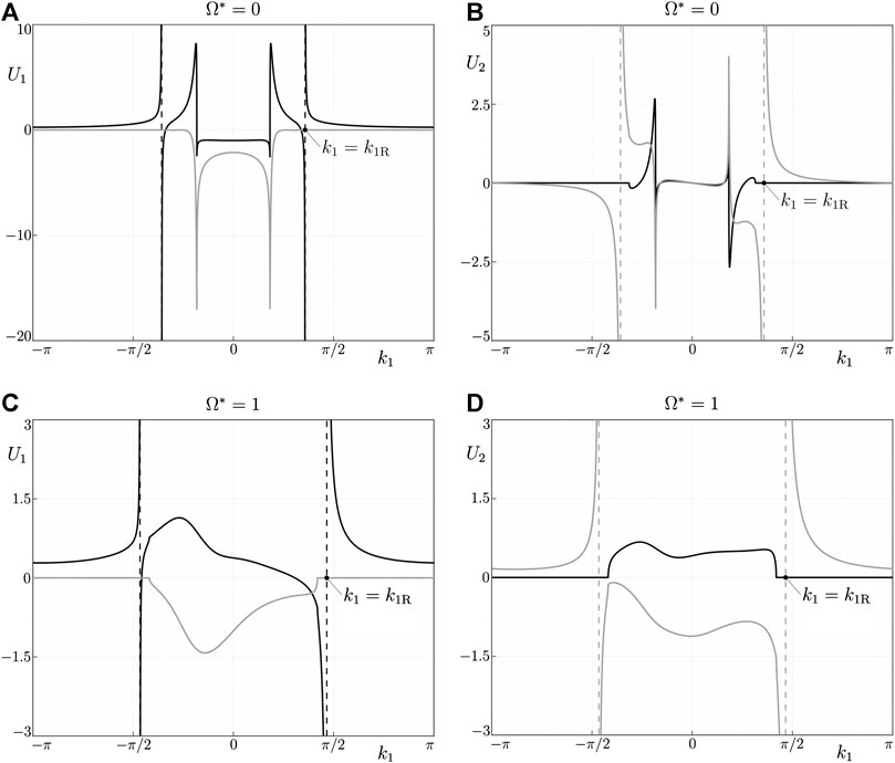
FIGURE 2. Plots of the discrete Fourier transform of the steady-state solution in Eq. 21, for
2.5 The Displacements in the Forced Lattice and Associated Wave Phenomena
The displacements in the lattice can be found from inverting the discrete Fourier transform, taking into account the periodicity properties of Eq. 21. Then, the displacements of the nodes in the lattice are given by
where
Here, we note that
2.5.1 The Rayleigh Waves
Rayleigh waves carry some of the energy produced by the point load in both directions along the boundary. The lack of symmetry in the integral kernel of Eq. 23 with respect to the zero wave number results in a disparity between amplitudes of waves outgoing from the source to the left and to the right of the load.
The Rayleigh waves are defined by the degenerate values of the wave number of
and represents the dispersion curve of the system associated with Rayleigh waves.1 The dispersion curve is plotted in Figure 3.
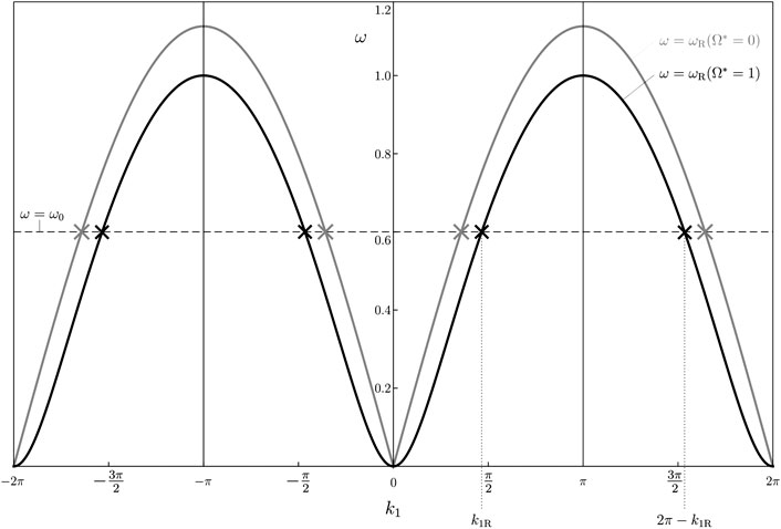
FIGURE 3. Dispersion diagram for
In Figure 3 we limit our attention to the intervals of periodicity for Eq. 21 mentioned in Section 2.4. Since
Using the above information, we can calculate the form of the Rayleigh waves produced by the point load by determining the simple poles of Eq. 23 and employing the residue theorem to compute Eq. 23 at a point located far from the application point of the oscillatory force. With this approach, it is possible to show that for
where the term on the right-hand side is the Rayleigh wave produced to the right of the point load. On the other hand, we have
where the right-hand side defines the Rayleigh wave traveling away from the load to the left. Here,
It can be verified that when
Hence, the resulting dynamic response at the boundary of the semi-infinite gyro-elastic lattice to the far left and right of the point load is different. Moreover, these outwardly-propagating boundary waves cause the nodes to follow elliptical trajectories, as shown by the eigenmode analysis developed by Nieves et al. (2020).
2.5.2 Bulk Wave Radiation
Waves are also radiated along the rows of the lattice in the bulk. As
For
where the term on the right-hand side describes a wave traveling along the row defined by
where the term on the right-hand side represents a wave propagating to the left along the row
For rows in the lattice defined by odd
whereas for
We point out that the amplitudes of the waves along the odd rows of the lattice, specified in Eqs. 32,33, take into account the contributions from the wave numbers
There also exist preferential directions for energy radiation in the bulk. When the gyricity is zero, along these specific lines in the lattice, the nodal displacements decay slowly as
2.5.3 Resonant Modes
Next, we discuss the resonant case when the steady-state solution to the considered problem does not exist. We show this by investigating the derived solution in Eq. 21 along the boundary, where
When
where
and
that indicates the appearance of other singular points near
We note that the singular points in this asymptote approach each other as the Laplace transform parameter
where
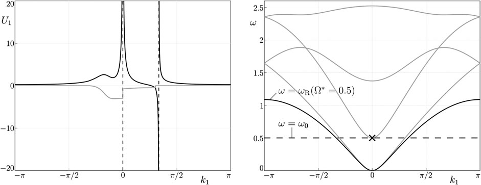
FIGURE 4. (A) The first component of the steady-state solution for the case of horizontal forcing on the boundary, with unit amplitude, when
The asymptotic representation in Eq. 36 is also in agreement with the dispersion diagram for
2.6 Determination of Energy Flow in the Steady-State Regime
In this section, we analyze the energy carried by the Rayleigh waves and by the waves radiated into the bulk of the gyroscopic lattice by calculating the energy flow through the boundary of a sufficiently large region of the medium, as shown in Figure 5. The considered region is the rectangle S enclosed by the half-plane boundary and by the segments
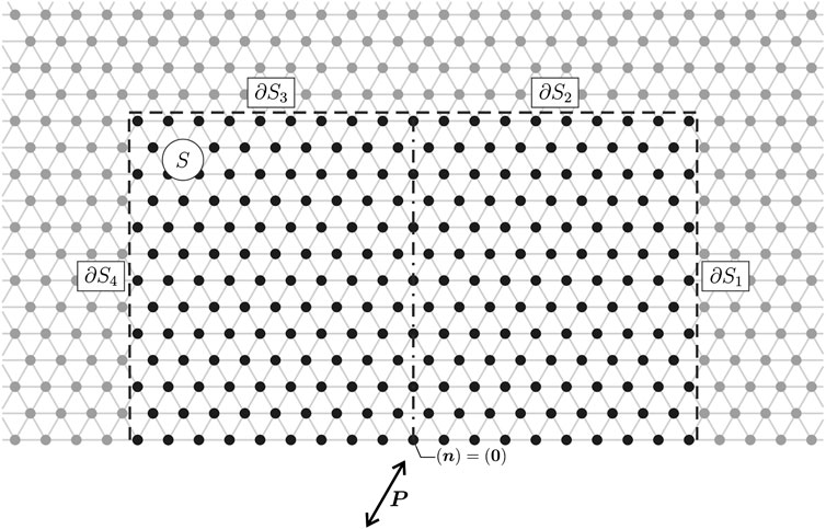
FIGURE 5. Region S of the gyroscopic lattice, delimited by the half-plane boundary and the segments
In the steady-state regime, the rate at which energy is introduced into the system through the action of an oscillating point load applied at the node
where the overline denotes the complex conjugate and
for
In Section 3, the above formulae for the energy flow will be used to show quantitatively that the presence of gyroscopic spinners breaks the symmetry of energy propagation with respect to a vertical line passing through the application point of the load.
2.7 Finite Element Model
The results of the analytical formulation illustrated in the previous sections will be verified with a finite element model built in the commercial software Comsol Multiphysics (version 5.4).
The numerical model consists of massless truss elements and point masses inserted at the lattice’s nodes. The effect of gyricity is simulated by imposing at each node a force that is proportional to the velocity, as in the first term on the right-hand side of the governing Eq. 2. Here the computational domain is finite, while the analytical treatment developed above is for a semi-infinite medium. In particular, the lattice has dimensions
3 Results
3.1 The Displacement Field in the Semi-Infinite Gyro-Elastic Lattice Loaded on the Boundary
In this section, we show the response of the semi-infinite lattice with embedded gyroscopic spinners to a point force applied on the boundary. In particular, we investigate how the gyricity affects the behavior of Rayleigh waves traveling along the boundary and of the waves propagating into the bulk of the medium.
Figure 6 shows the total displacement amplitude calculated at each node of the discrete system, produced by an oscillating force applied on the boundary. The results are based on the solution in Eq. 22, derived in Section 2. The force has unit amplitude and frequency
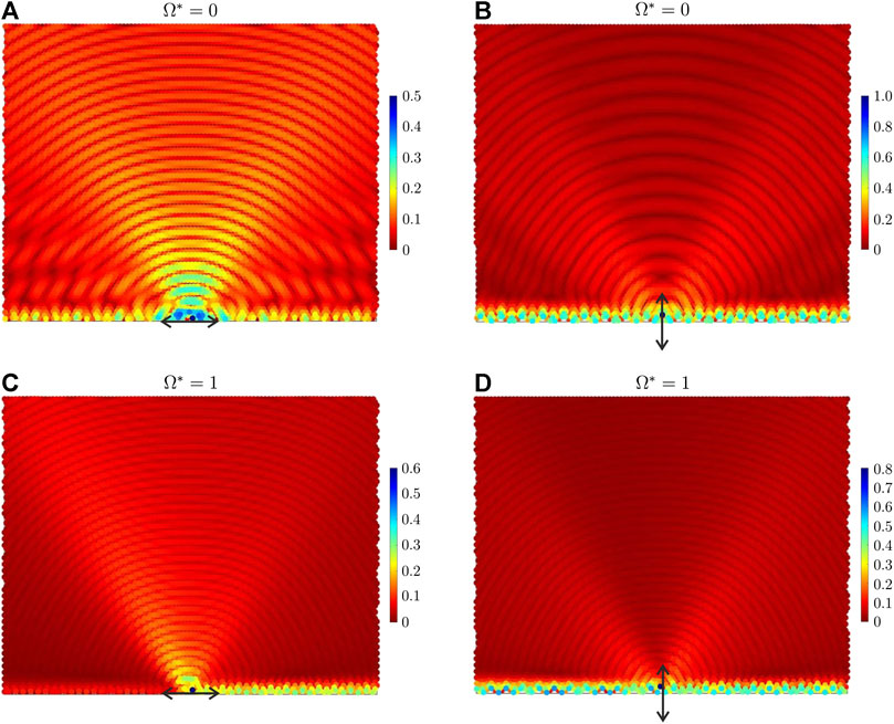
FIGURE 6. Total displacement amplitude field in the elastic lattice, obtained from the analytical formulation developed in Section 2, due to a (A,C) horizontal and (B,D) vertical point force applied on the boundary. In each figure, the force is represented by an arrow. The effective gyricity is (A,B)
In parts (A) and (B) of Figure 6 the effective gyricity is set equal to zero. It is apparent that when
Figures 6C,D illustrate the total displacement amplitude field produced by a horizontal and vertical force, respectively, when the effective gyricity is
We also point out that the non-symmetric displacement field in Figure 6 can be inverted by changing the sign of the effective gyricity
In Figure 7 we present the total displacement amplitude fields computed by using the finite element model developed in Comsol Multiphysics and described in Section 2.7. The values of the parameters are the same as those considered in Figure 6. Comparing Figures 6, 7, we observe that the numerical and analytical results show an excellent agreement. This confirms the validity and accuracy of the analytical treatment discussed in Section 2.
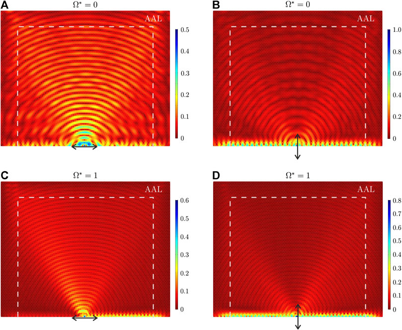
FIGURE 7. Same as in Figure 6, but obtained from numerical simulations performed in Comsol Multiphysics.
3.2 The Energy Flow
Here, we report the analytical results concerning the energy flow furnished by the external force, referred to as
As in Section 3.1, two different values of the effective gyricity are taken, namely
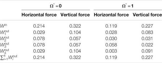
TABLE 1. Values of energy flows in the micro-structured lattice due to a horizontal or vertical force, when the effective gyricity is either
By looking at Table 1, we notice that when the effective gyricity is zero
3.3 Parametric Analysis
In order to assess how the response of the micro-structured medium is affected by different physical quantities, we perform a parametric analysis where we vary the direction of the force, the radian frequency
In Figure 8 we show how the energy introduced into the system by the external oscillating force is divided into two parts, propagating in opposite directions relative to the position of the point force. In particular, the circles (squares) indicate the percentages of the energy flowing to the right (left) of the force with respect to the input energy flow. In Figure 8 it is assumed that the force acts in the horizontal direction. The five diagrams correspond to
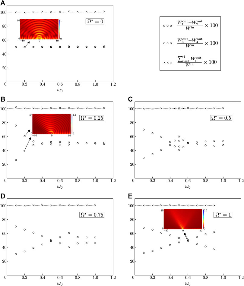
FIGURE 8. Percentages of energy flows propagating to the right (
In Figure 9 the values of the effective gyricity and of the frequency of the external source are identical to those considered in Figure 8, but the outcomes are obtained by applying a concentrated oscillating load acting in the vertical direction. In both Figures 8, 9, when
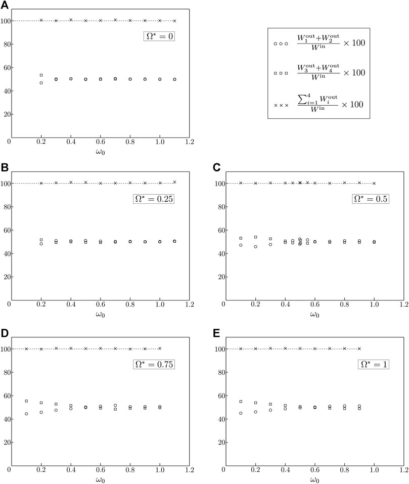
FIGURE 9. Same as in Figure 8, but for a vertically-acting point force.
The insets in Figure 8 present the color maps of the displacement fields, computed at given gyricities and frequencies of the external force. In part (A), where
In Figures 10, 11 we focus the attention on Rayleigh waves, showing how the contributions of the energy flows corresponding to surface waves traveling to the right (
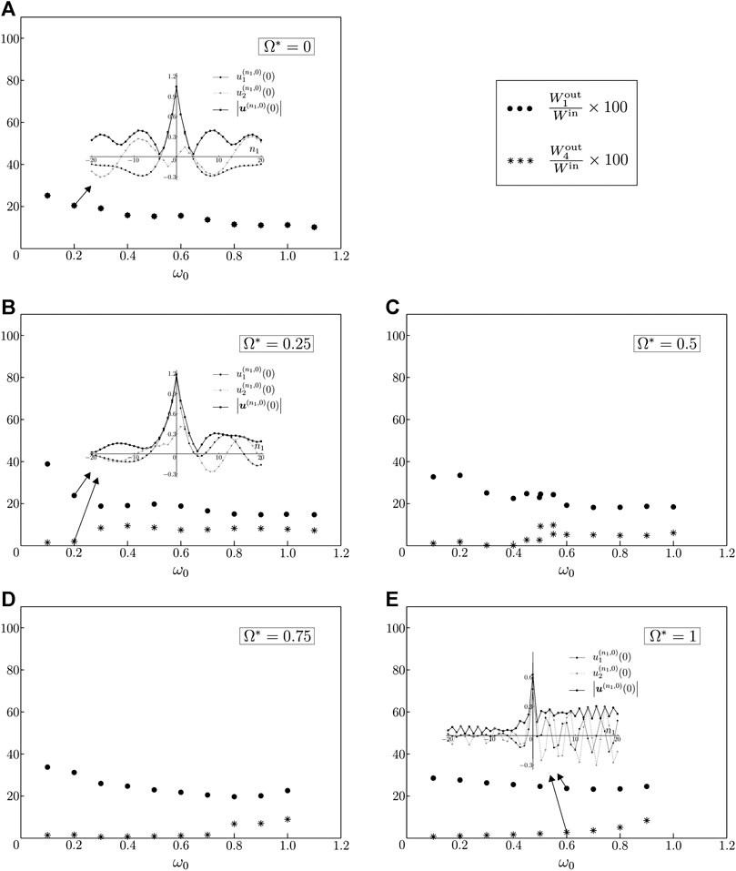
FIGURE 10. Energy flow percentages associated with Rayleigh waves traveling to the right and to the left of the point force, indicated by
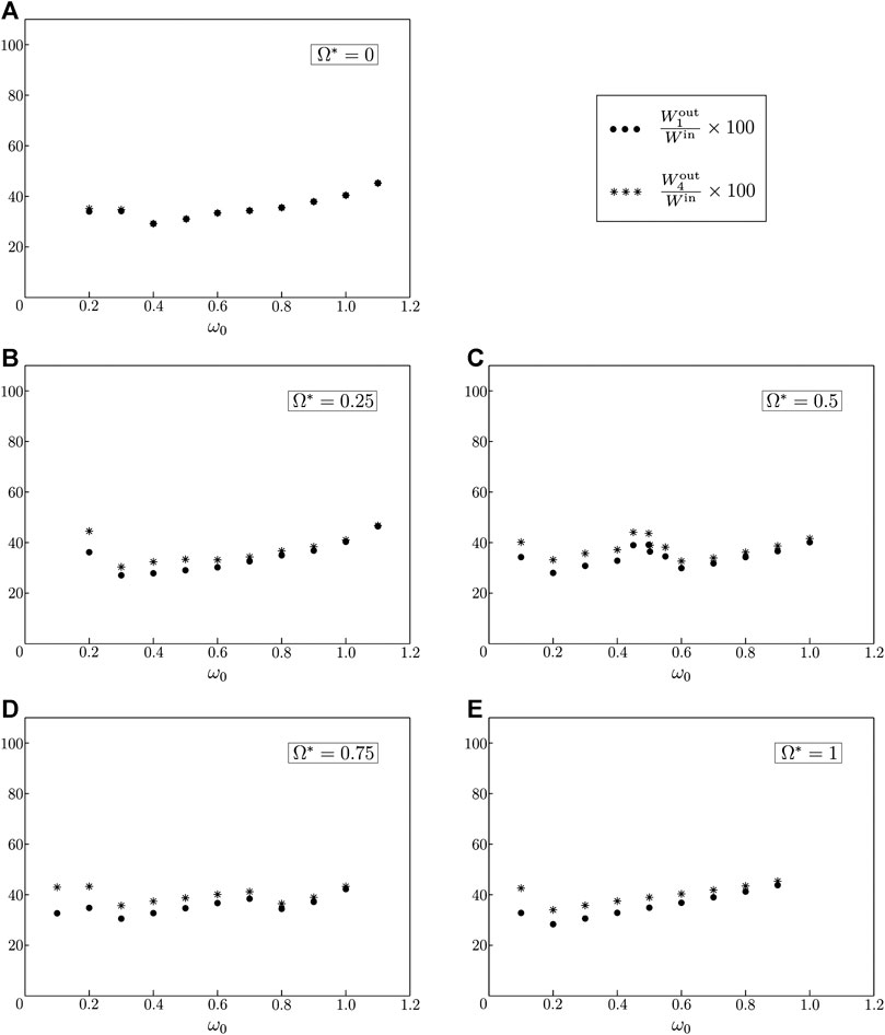
FIGURE 11. Same as in Figure 10, but for a vertically-acting point load.
The insets in Figure 10 illustrate, for different values of gyricity and frequency of the excitation, the amplitudes of the displacement components
Now, we consider a special case, where the surface waves propagating to the left of the point load exhibit a negligibly small amplitude. This can be obtained by taking the effective gyricity
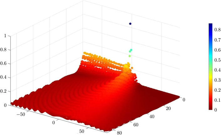
FIGURE 12. Displacement field of the lattice’s masses when
Another interesting case is represented by the scenario where almost all the energy propagates along the boundary. This situation is shown in Figure 13, where
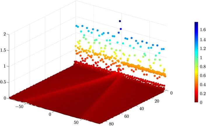
FIGURE 13. Displacement field of the lattice’s masses when
4 Discussion
The diagrams of the displacement amplitude fields in Figures 6, 7, as well as the values of the energy flows in Table 1, show that the gyricity is capable of breaking the symmetry in the energy propagation of both Rayleigh and bulk waves propagating from the external source. This is a consequence of the non-reciprocity of the gyro-elastic lattice.2
Examining the outcomes of the parametric analysis presented in Section 3.3, in particular Figures 8, 9, it is apparent that the distribution of energy in the system strongly depends on both the effective gyricity
The investigation of the individual components of the energy flows associated with Rayleigh waves, presented in Figures 10, 11 for a horizontally- and vertically-acting point force respectively, reveals that the propagation of energy along the boundary of the medium is affected significantly by the direction of the force. In the case when
The parametric analysis discussed in Section 3.3 has been helpful in identifying special cases, where Rayleigh waves propagate only in one direction (see Figure 12) or where bulk waves have very small amplitudes compared with those of surface waves (see Figure 13).
The analytical formulation also made it possible to analyze resonant regimes where the steady-state solution cannot be reached (see Section 2.5.3).
The capability of the considered micro-structured system in creating preferential directionality in the propagation of waves can be exploited to design novel energy splitters, where the desired amount of energy propagating in a specific prescribed direction can be varied by changing the effective gyricity of the spinners. The tunability of the proposed model is an essential tool, that can be used in many practical applications where it is required to vary the output depending on the contingent needs. Important examples include electronic instruments converting mechanical energy into electric energy (and vice versa) and elastic filters that can be utilized both for protection and energy harvesting.
Data Availability Statement
The original contributions presented in the study are included in the article/Supplementary Material, further inquiries can be directed to the corresponding author.
Author Contributions
All the authors contributed to the discussion of the results and the revision of the manuscript. MN had a leading role in the analytical development of the problem, GC in the numerical computations, VP in the physical interpretation of the model and MB in the conceptualization of the work.
Funding
MN and MB gratefully acknowledge the financial support of the EU H2020 grant MSCA-IF-2016-747334-CAT-FFLAP. The program “Mobilità dei giovani ricercatori” financed by Regione Autonoma della Sardegna is also acknowledged (MB and VP).
Conflict of Interest
The authors declare that the research was conducted in the absence of any commercial or financial relationships that could be construed as a potential conflict of interest.
Supplementary Material
The Supplementary Material for this article can be found online at: https://www.frontiersin.org/articles/10.3389/fmats.2020.602960/full#supplementary-material.
Footnotes
1The dispersion analysis for Rayleigh waves in a semi-infinite gyroscopic triangular lattice is discussed in detail by Nieves et al. (2020), where it is explicitly shown that the dispersion diagram remains symmetric.
2A formal proof of the non-reciprocity of the gyroscopic medium has been presented by Nieves et al. (2020).
References
Achenbach, J. D. (1973). “Wave propagation in elastic solids.” in North-holland series in applied mathematics and mechanics. Amsterdam, London: North-Holland Publishing Company, 16.
Al Ba’ba’a, H., Yu, K., and Wang, Q. (2020). Elastically-supported lattices for tunable mechanical topological insulators. Extreme Mechanics Letters. 38, 100758. doi:10.1016/j.eml.2020.100758
Antonakakis, T., Craster, R. V., Guenneau, S., and Skelton, E. A. (2014). An asymptotic theory for waves guided by diffraction gratings or along microstructured surfaces. Proc. Math. Phys. Eng. Sci. 470, 20130467. doi:10.1098/rspa.2013.0467
Armanini, C., Dal Corso, F., Misseroni, D., and Bigoni, D. (2017). From the elastica compass to the elastica catapult: an essay on the mechanics of soft robot arm. Proc. Math. Phys. Eng. Sci. 473, 20160870. doi:10.1098/rspa.2016.0870
Bacigalupo, A., De Bellis, M. L., and Gnecco, G. (2019). Complex frequency band structure of periodic thermo-diffusive materials by Floquet–Bloch theory. Acta Mech. 230, 3339–3363. doi:10.1007/s00707-019-02416-9
Bi, L., Hu, J., Jiang, P., Kim, D. H., Dionne, G. F., Kimerling, L. C., et al. (2011). On-chip optical isolation in monolithically integrated non-reciprocal optical resonators. Nat. Photon. 5, 758–762. doi:10.1038/nphoton.2011.270
Bordiga, G., Cabras, L., Piccolroaz, A., and Bigoni, D. (2018). Prestress tuning of negative refraction and wave channeling from flexural sources. Appl. Phys. Lett. 114. doi:10.1063/1.5084258
Brillouin, L. (1953). Wave propagation in periodic structuresElectric filters and crystal lattices. Mineola, NY: Dover Publications, Inc.
Brun, M., Jones, I. S., and Movchan, A. B. (2012). Vortex-type elastic structured media and dynamic shielding. Proc. Roy. Soc. Lond. 468, 3027–3046. doi:10.1098/rspa.2012.0165
Carta, G., Jones, I. S., Movchan, N. V., Movchan, A. B., and Nieves, M. J. (2017). Deflecting elastic prism” and unidirectional localisation for waves in chiral elastic systems. Sci. Rep. 7, 26. doi:10.1038/s41598-017-00054-6
Carta, G., Brun, M., Movchan, A. B., Movchan, N. V., and Jones, I. S. (2014). Dispersion properties of vortex-type monatomic lattices. Int. J. Solid Struct. 51, 2213–2225. doi:10.1016/j.ijsolstr.2014.02.026
Carta, G., Colquitt, D. J., Movchan, A. B., Movchan, N. V., and Jones, I. S. (2020). Chiral flexural waves in structured plates: directional localisation and control. J. Mech. Phys. Solid. 137, 103866. doi:10.1016/j.jmps.2020.103866
Carta, G., Colquitt, D. J., Movchan, A. B., Movchan, N. V., and Jones, I. S. (2019). One-way interfacial waves in a flexural plate with chiral double resonators. Philosophical Transactions of the Royal Society A. 378, 20190350. doi:10.1098/rsta.2019.0350
Carta, G., Nieves, M. J., Jones, I. S., Movchan, N. V., and Movchan, A. B. (2018). Elastic chiral waveguides with gyro-hinges. Q. J. Mech. Appl. Math. 71, 157–185. doi:10.1093/qjmam/hby001
Colquitt, D. J., Craster, R. V., Antonakakis, T., and Guenneau, S. (2015). Rayleigh-Bloch waves along elastic diffraction gratings. Proc. Math. Phys. Eng. Sci. 471, 20140465. doi:10.1098/rspa.2014.0465
Filipov, E. T., Tachi, T., Paulino, G. H., and Weitz, D. A. (2015). Origami tubes assembled into stiff, yet reconfigurable structures and metamaterials. Proc. Natl. Acad. Sci. U.S.A. 112, 12321–12326. doi:10.1073/pnas.1509465112
Fleury, R., Sounas, D. L., Sieck, C. F., Haberman, M. R., and Alù, A. (2014). Sound isolation and giant linear nonreciprocity in a compact acoustic circulator. Science. 343, 516–519. doi:10.1126/science.1246957
Garau, M., Carta, G., Nieves, M. J., Jones, I. S., Movchan, N. V., and Movchan, A. B. (2018). Interfacial waveforms in chiral lattices with gyroscopic spinners. Proc. Roy. Soc. Lond. 474, 20180132. doi:10.1098/rspa.2018.0132
Garau, M., Nieves, M. J., Carta, G., and Brun, M. (2019). Transient response of a gyro-elastic structured medium: unidirectional waveforms and cloaking. Int. J. Eng. Sci. 143, 115–141. doi:10.1016/j.ijengsci.2019.05.007
Graff, K. F. (1975). Wave motion in elastic solids. Oxford, United Kingdom: Oxford University Press.
Haslinger, S. G., Movchan, N. V., Movchan, A. B., Jones, I. S., and Craster, R. V. (2017). Controlling flexural waves in semi-infinite platonic crystals with resonator-type scatterers. Q. J. Mech. Appl. Math. 70, 216–247. doi:10.1093/qjmam/hbx005
Lee, C. H., Li, G., Jin, G., Liu, Y., and Zhang, X. (2018). Topological dynamics of gyroscopic and Floquet lattices from Newton’s laws. Phys. Rev. B. 97, 085110. doi:10.1103/PhysRevB.97.085110
Linton, C. M., and McIver, M. (2002). The existence of Rayleigh-Bloch surface waves. J. Fluid Mech. 470, 85–90. doi:10.1017/S0022112002002227
Marder, M., and Gross, S. (1995). Origin of crack tip instabilities. J. Mech. Phys. Solid. 43, 1–48. doi:10.1016/0022-5096(94)00060-I
Misseroni, D., Colquitt, D. J., Movchan, A. B., Movchan, N. V., and Jones, I. S. (2016). Cymatics for the cloaking of flexural vibrations in a structured plate. Sci. Rep. 6, 23929. doi:10.1038/srep23929
Mitchell, N. P., Nash, L. M., and Irvine, W. T. M. (2018). Tunable band topology in gyroscopic lattices. Phys. Rev. B. 98, 174301. doi:10.1103/PhysRevB.98.174301
Morvaridi, M., Carta, G., and Brun, M. (2018). Platonic crystal with low-frequency locally-resonant spiral structures: wave trapping, transmission amplification, shielding and edge waves. J. Mech. Phys. Solid. 121, 496–516. doi:10.1016/j.jmps.2018.08.017
Nash, L. M., Kleckner, D., Read, A., Vitelli, V., Turner, A. M., and Irvine, W. T. (2015). Topological mechanics of gyroscopic metamaterials. Proc. Natl. Acad. Sci. U.S.A. 112, 14495–14500. doi:10.1073/pnas.1507413112
Nieves, M. J., Carta, G., Jones, I. S., Movchan, N. V., and Movchan, A. B. (2018). Vibrations and elastic waves in chiral multi-structures. J. Mech. Phys. Solid. 121, 387–408. doi:10.1016/j.jmps.2018.07.020
Nieves, M. J., Carta, G., Pagneux, V., and Brun, M. (2020). Rayleigh waves in micro-structured elastic systems: non-reciprocity and energy symmetry breaking. Int. J. Eng. Sci. 156, 103365. doi:10.1016/j.ijengsci.2020.103365
Nieves, M. J., Movchan, A. B., Jones, I. S., and Mishuris, G. S. (2013). Propagation of Slepyan’s crack in a non-uniform elastic lattice. J. Mech. Phys. Solid. 61, 1464–1488. doi:10.1016/j.jmps.2012.12.006
Piccolroaz, A., Gorbushin, N. A., Mishuris, G. S., and Nieves, M. J. (2020). Dynamic phenomena and crack propagation in dissimilar elastic lattices. Int. J. Eng. Sci. 149, 103208. doi:10.1016/j.ijengsci.2019.103208
Porter, R., and Evans, D. V. (2005). Embedded Rayleigh-Bloch surface waves along periodic rectangular arrays. Wave Motion. 43, 29–50. doi:10.1016/j.wavemoti.2005.05.005
Porter, R., and Evans, D. V. (1999). Rayleigh-Bloch surface waves along periodic gratings and their connection with trapped modes in waveguides. J. Fluid Mech. 386, 233–258. doi:10.1017/S0022112099004425
Rayleigh, J. W. S. (1885). On waves propagated along the plane surface of an elastic solid. Proc. Lond. Math. Soc. 17, 4–11. doi:10.1112/plms/s1-17.1.4
Slepyan, L. I. (2010). Wave radiation in lattice fracture. Acoust Phys. 56, 962–971. doi:10.1134/S1063771010060217
Sounas, D. L., Caloz, C., and Alù, A. (2013). Giant non-reciprocity at the subwavelength scale using angular momentum-biased metamaterials. Nat. Commun. 4, 2407. doi:10.1038/ncomms3407
Süsstrunk, R., and Huber, S. D. (2015). Observation of phononic helical edge states in a mechanical topological insulator. Science 349, 47–50. doi:10.1126/science.aab0239
Tallarico, D., Hannema, G., Miniaci, M., Bergamini, A., Zemp, A., and Van Damme, B. (2020). Superelement modelling of elastic metamaterials: complex dispersive properties of three-dimensional structured beams and plates. J. Sound Vib. 484, 115499. doi:10.1016/j.jsv.2020.115499
Wang, P., Lu, L., and Bertoldi, K. (2015). Topological phononic crystals with one-way elastic edge waves. Phys. Rev. Lett. 115, 104302. doi:10.1098/rspa.2018.0132
Keywords: Rayleigh waves, elastic lattice, gyroscopic spinners, dispersion properties, energy flow, non-reciprocity, energy symmetry breaking
Citation: Nieves MJ, Carta G, Pagneux V and Brun M (2021) Directional Control of Rayleigh Wave Propagation in an Elastic Lattice by Gyroscopic Effects. Front. Mater. 7:602960. doi: 10.3389/fmats.2020.602960
Received: 04 September 2020; Accepted: 05 November 2020;
Published: 27 January 2021.
Edited by:
Andrea Bacigalupo, University of Genoa, ItalyReviewed by:
Andrea Colombi, ETH Zürich, SwitzerlandEnrico Radi, University of Modena and Reggio Emilia, Italy
Copyright © 2021 Nieves, Carta, Pagneux and Brun. This is an open-access article distributed under the terms of the Creative Commons Attribution License (CC BY). The use, distribution or reproduction in other forums is permitted, provided the original author(s) and the copyright owner(s) are credited and that the original publication in this journal is cited, in accordance with accepted academic practice. No use, distribution or reproduction is permitted which does not comply with these terms.
*Correspondence: G. Carta, Z2lvcmdpb19jYXJ0YUB1bmljYS5pdA==